智能小车行驶系统设计(含CAD零件装配图,CATIA三维图)(任务书,开题报告,文献摘要,外文翻译,论文说明书14000字,CAD图6张,CATIA三维图)
摘要
智能车技术已成当前热门,实验室内通常使用智能小车作为实验平台,本文介绍一套智能小车行驶系统的设计流程。文章以国内外研究现状为起,调研智能车辆技术发展现状,分析确定本小车设计要求;详细介绍了车架结构、驱动系统、转向系统以及底层控制系统的设计过程。
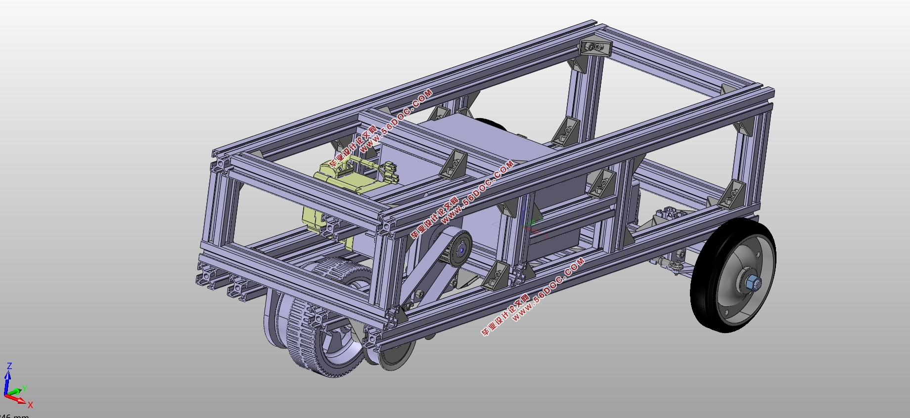
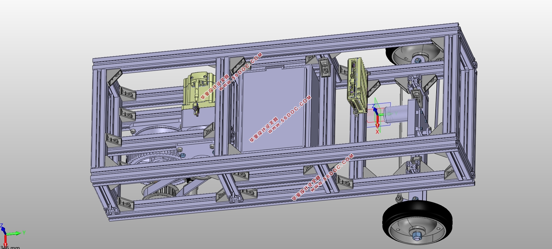
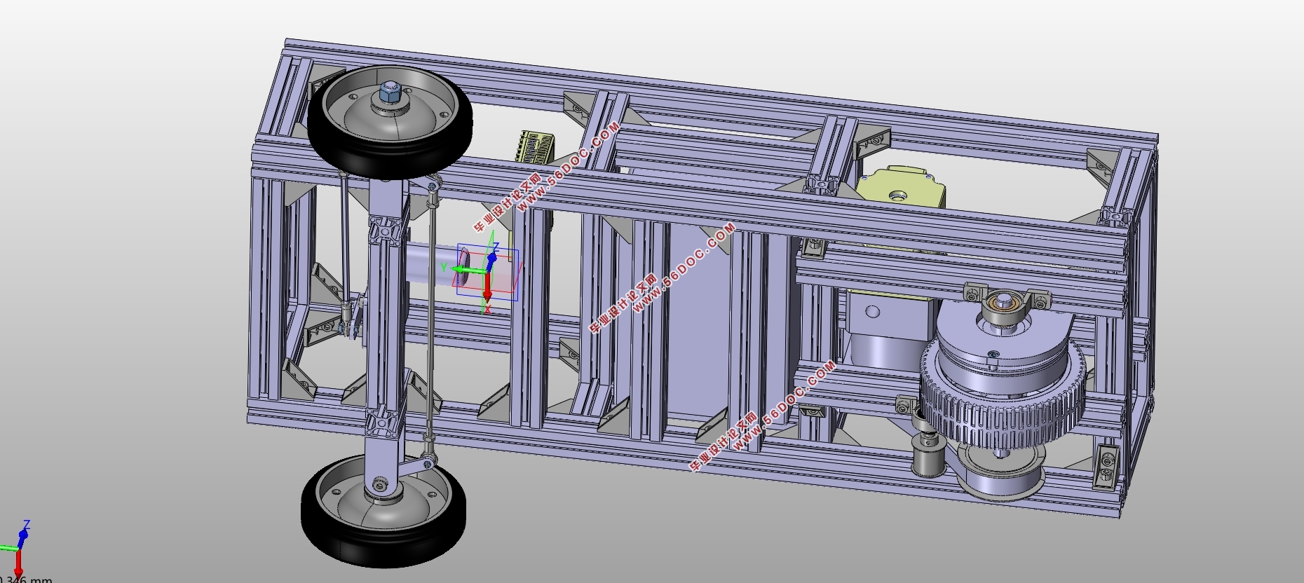
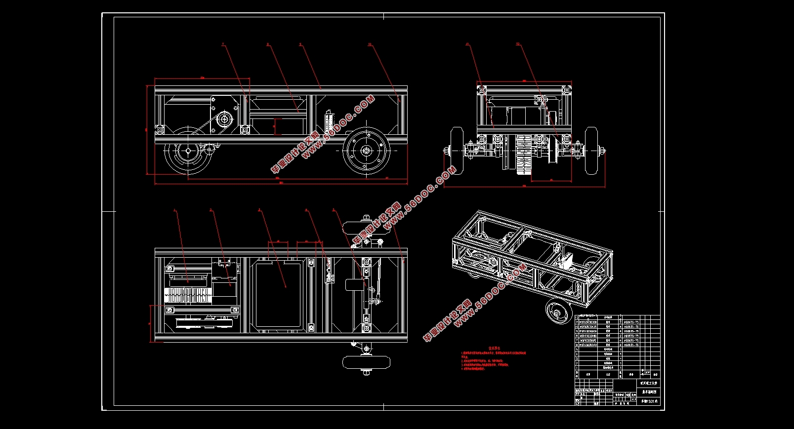
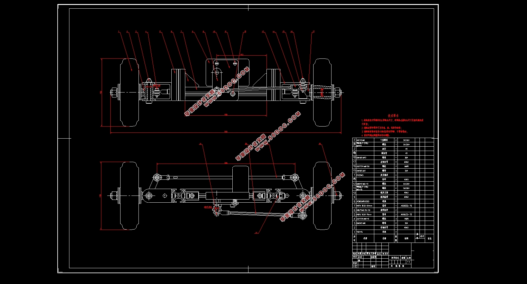
该小车以铝型材为框架,将整车分为三个模块,采用前轮转向、后轮集中式驱动、电池中置的整车布置方案,采用单后轮驱动以解决转向差速问题。驱动系统以电动机为动力来源,同步带传动方式实现传动,能够保证传动精度的前提下降低噪音,配备了失电制动器,保证紧急情况车辆安全,并对驱动轴进行强度校核。转向系统采用整体式转向梯形,利用舵机提供转向动力。设计时,根据转向梯形评价函数,利用MATLAB辅助计算,对梯形参数进行优化设计,根据转向机构空间关系,建立了舵机转角和车轮转角的数学关系,并针对转向节进行应力分析。文章最后介绍了以STM32控制板为核心的控制系统硬件组成、测速原理、电机控制特性、速度和转向控制算法,利用PID控制算法,实现速度控制,脉宽调制实现舵机角度控制。
关键词:智能小车;驱动系统;运动控制;
Abstract
Smart car technology has become a hot topic. The smart car is usually used as an experimental platform in the laboratory. This paper introduces the design process of a smart car driving system. Based on the research status at home and abroad, this paper investigates the development status of intelligent vehicle technology, analyzes and determines the design requirements of this car, and introduces the design process of frame structure, drive system, steering system and bottom control system in detail.
The car is framed by aluminum profiles, and the whole car is divided into three modules. It adopts front wheel steering, rear wheel centralized drive, and battery-mounted vehicle layout scheme, and adopts single rear wheel drive to solve the steering differential problem. The drive system uses the electric motor as the power source, and the synchronous belt transmission mode realizes the transmission. It can reduce the noise under the premise of ensuring the transmission precision. It is equipped with a power-off brake to ensure the safety of the vehicle in an emergency situation and to check the strength of the drive shaft. The steering system uses an integral steering trapezoid and uses the steering gear to provide steering power. In the design, according to the steering trapezoid evaluation function, the MATLAB auxiliary calculation is used to optimize the trapezoidal parameters. According to the spatial relationship of the steering mechanism, the mathematical relationship between the steering angle and the wheel angle is established, and the stress analysis is carried out for the steering knuckle. Finally, the paper introduces the control system hardware composition, speed measurement principle, motor control characteristics, speed and steering control algorithm with STM32 control board as the core. The PID control algorithm is used to realize speed control and pulse width modulation to realize steering angle control.
Key words: Smart car; drive system; motion control;
设计目标分析
本设计智能小车采用电驱动方式,以电池为能量源,电机为动力单元。城市铺装道路、高速公路和特殊环境道路是目前智能车辆的主要行驶工况。本智能小车主要针对校园内良好铺装的沥青路面,设计初期对小车提出100kg的负载要求。同时,为方便后期实验设备的安装,该小车应具有良好的扩展性。
智能小车的底层控制可分为横向控制和纵向控制两个部分,实现小车速度和方向的控制是实现自动驾驶的基础。针对小车驱动系统,应使小车能达到10km/h的车速,能够达到最高车速以下任意设定车速并稳定行驶,爬坡能力超过7%。针对小车转向系统,应使小车转向尽可能灵活,有较小的转弯半径,能使转向轮达到设定转角。
本文主要内容
本文针对一款智能小车行驶系统的设计过程进行详细介绍,包括结构设计、控制系统设计及算法介绍。
第一章介绍了智能车的发展背景以及国内外研究现状,分析确定了小车的设计目标。
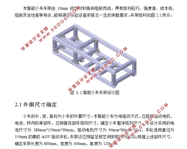
第二章介绍了小车车架的设计流程,确定了小车基本外廓尺寸、轴距、轮距等参数。
第三章介绍了驱动系统的设计,包括驱动形式的选择、小车动力分析、电机选型、制动机构设计、电池参数计算等,并对驱动轴进行强度校核。
第三章介绍了转向系统的设计,包括转向形式选择、梯形参数优化、转角数学关系、转向节强度校核等。
第四章介绍了控制系统的整体设计,包括控制系统软硬件平台、电机和舵机控制原理及控制方法等等。
目录
摘要 I
Abstract II
目录 III
第 1 章绪论 1
1.1 引言 1
1.2 国内外研究现状 1
1.2.1 国外研究现状 1
1.2.2 国内研究现状 2
1.3 设计目标分析 2
1.4 本文主要内容 3
第 2 章车架设计 4
2.1 外廓尺寸确定 4
2.2 轴距和轮距确定 4
2.3 车架布置形式 5
2.4 本章小结 5
第 3 章驱动系统设计 6
3.1 驱动方式选择 6
3.2 驱动电机选择 8
3.3 传动形式设计 9
3.4 小车运动分析 12
3.4.1 驱动力分析 12
3.4.2 最高车速计算 14
3.4.3 计算最大爬坡度 14
3.4.4 最大加速度 14
3.5 制动机构设计 15
3.6 驱动轴校核 15
3.7 电池参数计算 16
3.8 本章小结 16
第 4 章转向机构设计 17
4.1 转向梯形设计 17
4.2 舵机选择 22
4.3 转向节设计 24
4.4 本章小结 25
第 5 章驱动控制系统设计 26
5.1 控制系统硬件组成 26
5.2 软件开发平台 26
5.3 驱动系统控制 27
5.3.1 直流无刷电机特性 27
5.3.2 PWM调速原理 28
5.3.3 测速方法 29
5.3.4 控制算法 29
5.4 转向系统控制 30
5.5 本章小结 31
第 6 章总结和展望 32
致谢 33
参考文献 34
|