6t���綯�����ػ��������ܳ����(Ӣ�İ�)(��CAD���ͼװ��ͼ)
��Դ��wenku7.com ���ϱ�ţ�WK718846 ���ϵȼ��������� %E8%B5%84%E6%96%99%E7%BC%96%E5%8F%B7%EF%BC%9AWK718846
���������Ͻ���,����Ҫ���������ֵ���ء�
1.����ע���¼,֧��������ʾ�������ɻ�ȡ������.
2.��������ҳ���ܵ�Ϊ,���غ���ˮӡ.���Ͻ���ѧϰ�ο�֮��. �� �� �� ����
���Ͻ���
6t���綯�����ػ��������ܳ����(Ӣ�İ�)(��CAD���ͼװ��ͼ)(������,���ⱨ��,����˵����Ӣ�İ�9000��,CADͼ6��)
ժ Ҫ
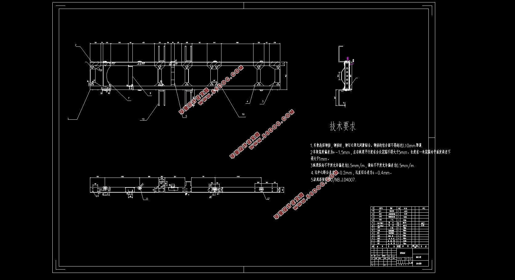
�����о����ǵ綯�ػ������ܣ����ڴ�ͳ�����Ի����IJ��Ѻò����Ѿ��ﵽ�˷�չƿ����Խ��Խ����о��������ڵ綯�������綯�����������ù����Ƚ��ĵ���Ϳ��Ƽ�����ʹ�������������������ǿ�����ص㣬��������ظ���֤���䳬������ʻ��̣���ǿ�ĵ������ʹ�䰲ȫ���ܸ����ȶ������̵������dz��ܣ����������Ļ��壬ͨ�����������������ͼ���������ɵģ���������װ�épǰ�ũp����֧���ڳ����ϡ�ӵ���㹻�ĸնȺ�ǿ���������������غɺʹӳ��ִ����ij������˳��ܵĸնȺ�ǿ��������������������ŷdz���Ҫ�����á�������Ҫ�о��������ػ������ij����ܳ���ƣ����ĶԳ��ܽ�������ά��ģ����ansys��������Ԫ������
�ؼ��ʣ��綯�ػ��������ܣ���ά��ģ������Ԫ����
Abstract
The frame of electric truck is studied in this paper. Because the traditional vehicle is not friendly to the environment and has reached the bottleneck of development, more and more research tends to electric truck. Most of the electric trucks adopt foreign advanced motor and control technology, which makes them have the characteristics of large load and stronger power. The large capacity battery guarantees its long driving range, and the strong chassis design makes its safety more stable. The theme of the chassis is the frame, which is the base of the car. Usually it is composed of two Frame rails and several crossmember. It is supported on the wheels by suspension device, front axle and rear axle. With enough stiffness and strength to withstand the load of the car and the impact from the wheel, the stiffness and strength of the frame plays a very important role in the overall design of the car. This paper mainly studies the frame assembly design of light truck. In this paper, the three-dimensional model of the frame is built and the finite element analysis is done with ansys.
Key Words��electric truck;frame;3d model;finite element analysis

List
Chapter 1 Introduction........................................................................................................................1
1.1 Research background of electric truck.........................................................................................1
1.2 Research status of electric truck...................................................................................................1
1.2.1 Current status of foreign research..............................................................................................1
1.2.2 Current status of domestic research...........................................................................................2
1.3 Research background of frame design..........................................................................................2
1.4 Research Purpose and Significance..............................................................................................3
1.5 Basic content and objectives.........................................................................................................3
Chapter 2 Types and Parameters of Electric Freight Vehicles.............................................................4
2.1 Electric truck model.......................................................................................................................4
2.2 Vehicle parameters.........................................................................................................................4
2.2.1 Body parameter...........................................................................................................................4
2.2.2 Motor parameters........................................................................................................................4
2.2.3 Container parameters..................................................................................................................5
Chapter3 Frame Design.......................................................................................................................6
3.1 Frame Design Requirements..........................................................................................................6
3.2 Force Type of Frame......................................................................................................................7
3.3 Types of Frame...............................................................................................................................7
3.4 Types of crossmember and Frame rails..........................................................................................8
3.5 Structural Design of Frame rail......................................................................................................9
3.5.1 Selection of Frame Length and Material.....................................................................................9
3.5.2 Calculating the Section Size of Frame rail..................................................................................9
3.5.3 Design and Strength Check of Frame rail.................................................................................11
3.5.4 Rigidity Check of Frame rail....................................................................................................13
3.6 Establishment of Three-Dimensional Frame Model....................................................................15
3.6.1 Establishment and View of Three-dimensional Model.............................................................15
3.6.2 Modeling of Frame rail.............................................................................................................15
3.6.3 Modeling of Front crossmember...............................................................................................16
3.6.4 Modeling of Supporting crossmember......................................................................................16
3.6.5 Modeling of Steel panel...........................................................................................................17
3.6.6 Modeling of middle and rear crossmembers.............................................................................17
3.6.7 General Assembly Model..........................................................................................................18
3.7 conclusion....................................................................................................................................18
Chapter4 Finite Element Analysis......................................................................................................19
4.1 finite element modeling..............................................................................................................19
4.2 finite element static analysis.......................................................................................................19
4.2.1 bendingconditions...................................................................................................................20
4.2.2 Torsional conditions.................................................................................................................21
4.2.3 emergency brake conditions.....................................................................................................22
4.3 finite element modal analysis......................................................................................................23
4.4 conclusion....................................................................................................................................26
Chapter5Improvement model...........................................................................................................27
5.1 Improvement scheme...................................................................................................................27
5.2 Improvement model.....................................................................................................................27
5.2.1 front and rear crossmember.......................................................................................................27
5.2.2 Front Support Plate crossmember of Rear Suspension.............................................................27
5.2.3 Secondcrossmemberagainst torsion........................................................................................28
5.2.4 new assembly frame..................................................................................................................28
5.3 Simulation test.............................................................................................................................29
5.3.1 bendingconditions...................................................................................................................29
5.3.2 Torsional conditions..................................................................................................................29
5.4 conclusion....................................................................................................................................30
Reference...........................................................................................................................................31
Thanks................................................................................................................................................32
|