WG7202四驱中级轿车后悬架设计(含CAD图,SolidWorks三维图)(任务书,开题报告,文献摘要,外文翻译,论文说明书16000字,CAD图8张,SolidWorks三维图)
摘要
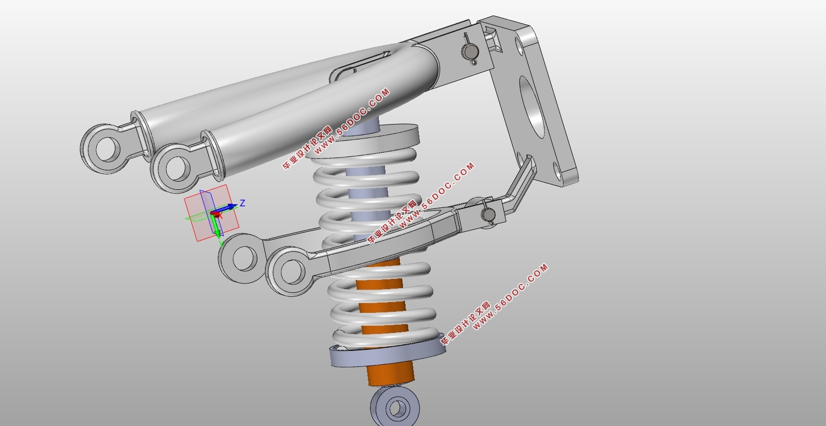
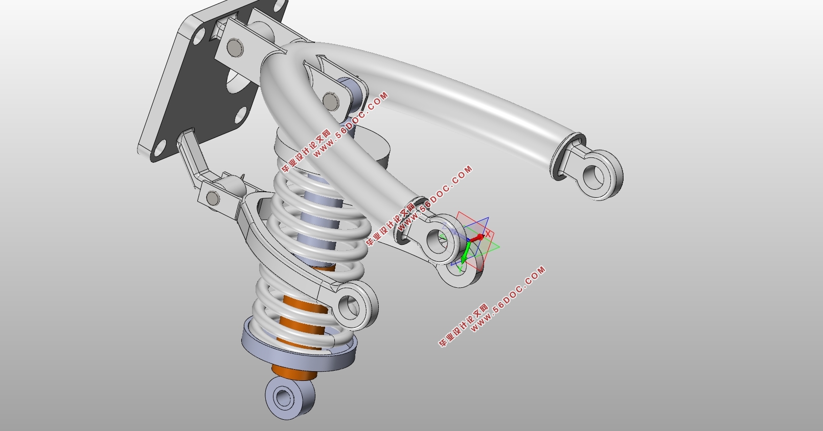
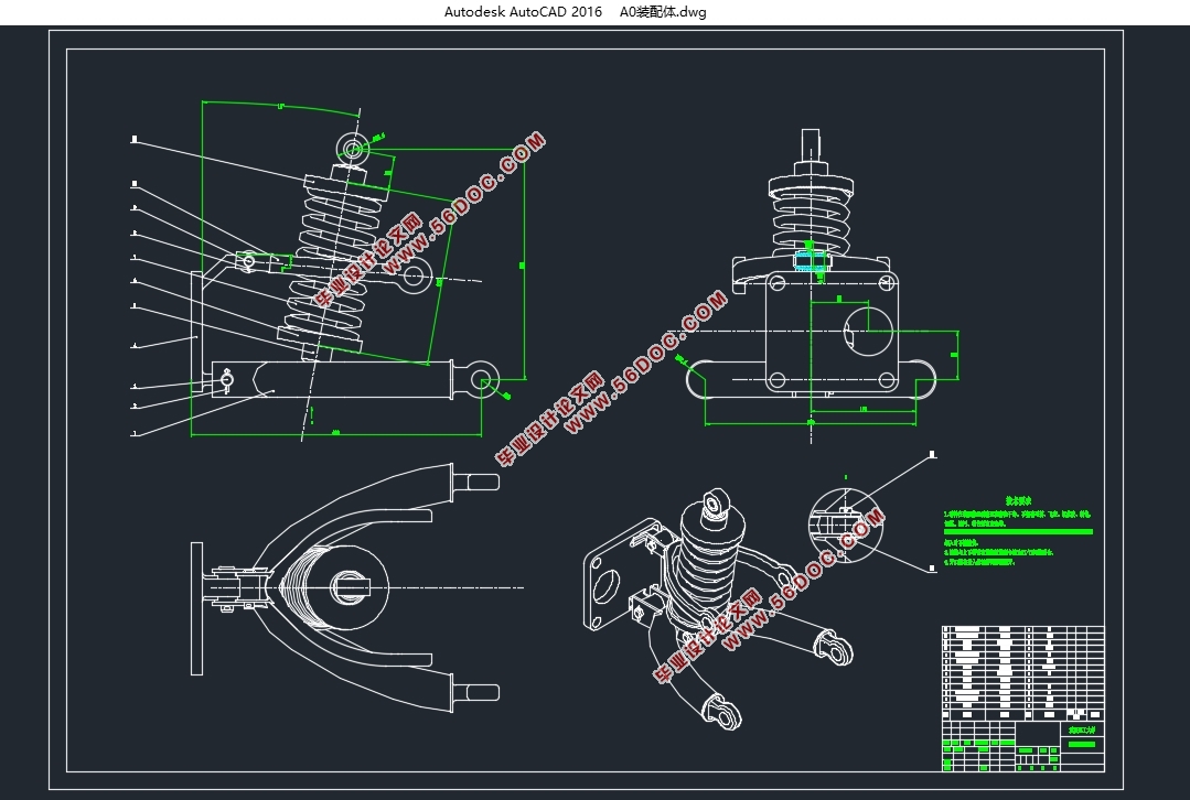
悬架是汽车的重要组成之一,它将车轴(或车轮)与车架(或车身)弹性地连接起来,传递车轮和车架之间的力和力矩。本文是针对四驱中级轿车后悬架的设计,这里参考本田CRV轿车的后悬,选用了双横臂独立悬架,它的两个摆臂在汽车的横向平面内摆动,适当的选取上下臂的长度,可以让车轮在行驶过程中,轮距保持不变,轮胎的磨损减小,还能保证良好的行驶稳定性。本说明书中包括悬架设计的目的及意义,悬架的系统组成,独立悬架与非独立悬架的选择,悬架具体结构形式的选择,悬架参数的计算,导向机构的计算,弹性元件的具体计算,减振器的具体计算。运用ADAMS对悬架进行仿真分析,保证设计出的悬架符合要求。
关键词:双横臂独立悬架;螺旋弹簧;双筒式减振器;导向机构;ADAMS
Abstract
Suspension is one of the important components of the car, it willconnect axle (or wheel) and the frame (or body) elastically, passing the force and torquebetween wheels and the frame.This thesisis written about the four-wheel drive rear suspension design, which references Honda CRV car rear suspension. I choose double wishbone independent suspension, and its two armsswing in the car's horizontal plane.Appropriate selection of the length of the upper and lower arm can make the tread remain the same in the process of running, decrease the wear and tear of the tire, and ensure good driving stability.This thesisincludes the purpose and significance of the suspension design, the composition of the suspensionsystem, the choice of independent suspension and the non-independent suspension, the choice of the specific structure of the suspension, the calculation of the suspension parameters, the calculation of the guide mechanism, the specific calculation of the elastic element, and the specific calculation of the shock absorber.And then ADAMS isusedto simulate the suspension to ensure that the design of the suspension to meet the requirements.
Keywords:double wishbone independent suspension;spiral spring;double-barrel shock absorber; guide mechanism;ADAMS
整车参数
尺寸参数 长/宽/高/(mm) 4575/1820/1680
轴距(mm) 2620
轮距(前/后)(mm) 1565/1565
质量参数 整备质量(kg) 1555
满载总质量(kg) 2010
性能参数 最高车速(km/h) 182
0-100km/h加速时间(s) 10.39
最大爬坡度(%) 30


目录
第1章绪论 1
1.1课题研究的目的和意义 1
1.2国内外研究现状 1
1.3设计的基本内容和目标 2
1.3.1设计的基本内容 2
1.3.2设计的目标 2
第2章悬架选型 3
2.1悬架系统的作用和组成 3
2.2独立悬架与非独立悬架的选择 3
2.3悬架具体结构形式的选择 3
第3章悬架参数选择 5
3.1悬架静挠度 5
3.2悬架动挠度 6
3.3簧上质量 6
3.4悬架刚度 7
第4章导向机构设计 8
4.1导向机构的设计要求 8
4.2导向机构尺寸的设计 8
4.3导向机构侧倾中心高度的设计 9
4.4导向机构在纵向平面内的布置 10
4.5导向机构在水平面内的布置 11
第5章弹性元件设计 12
5.1弹性元件的作用及分类 12
5.2螺旋弹簧参数设计 12
5.2.1弹簧刚度 12
5.2.2弹簧钢丝直径 13
5.2.3弹簧工作圈数 14
5.3螺旋弹簧的校核 14
第6章减振器设计 16
6.1减振器的分类 16
6.2减振器的参数设计 16
6.2.1相对阻尼系数 16
6.2.2减振器阻尼系数 17
6.2.3最大卸荷力 18
6.2.4主要尺寸参数 18
第7章悬架仿真 19
7.1轮距变化的仿真 19
7.2车轮外倾变化的仿真 20
第8章导向机构受力分析与强度校核 22
8.1单个作用力作用时的受力分析 22
8.1.1车轮只有垂直力FV作用 22
8.1.2车轮只有侧向力FL作用 23
8.1.3车轮只有驱动力FA作用 24
8.1.4车轮只有制动力FB作用 25
8.2四种工况的受力分析 26
8.2.1最大垂直力工况 26
8.2.2最大侧向力工况 27
8.2.3最大驱动力工况 28
8.2.4最大制动力工况 29
8.3强度校核 30
8.3.1上横臂的校核 30
8.3.2下横臂的校核 31
8.3.3连接板的校核 32
结论 33
参考文献 34
附录 35
致谢 42
|


