祁阳绕城公路跨沿江路立交桥设计(34.44+60×3+42.83m)(含CAD图纸)(任务书,开题报告,论文说明书24000字,CAD图纸48张,PDF图48张)
摘要
本次毕业设计的题目是祁阳绕城公路跨沿江路立交桥设计,对该桥梁主桥部分的上部机构和下部结构进行相应的设计计算并绘制施工图纸。
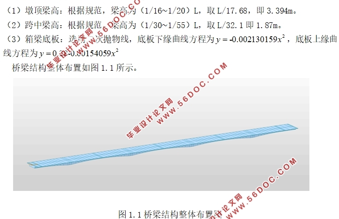
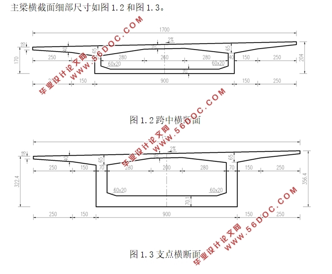
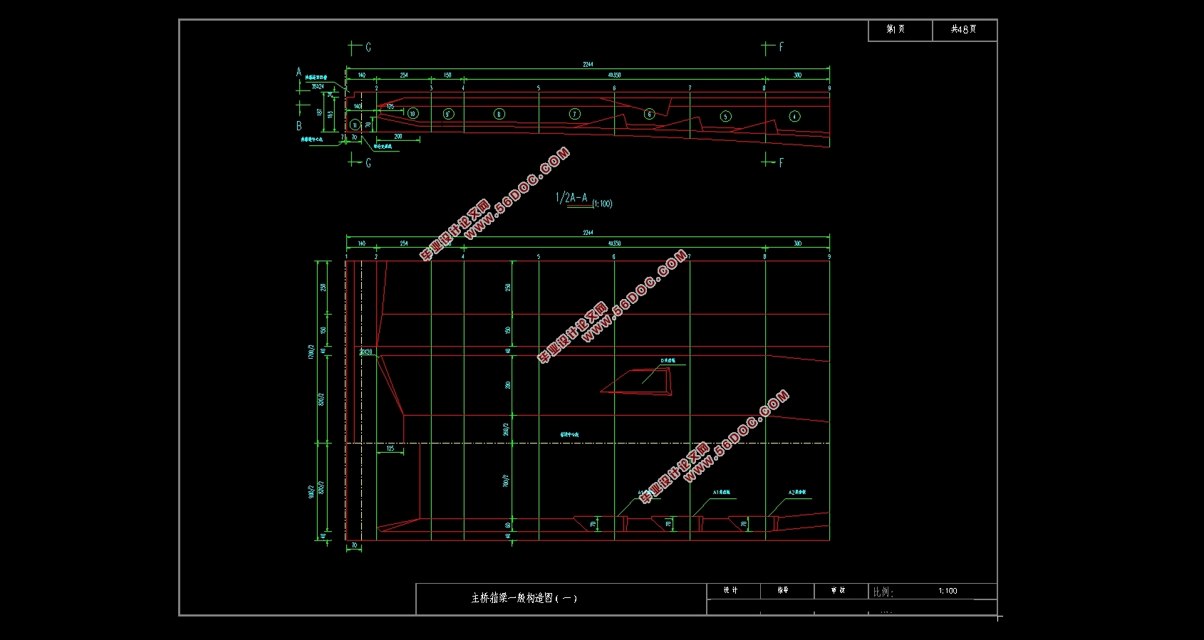
根据相关规范要求,本设计拟定了主梁、主墩和基础桩的细部尺寸。主梁截面采用单箱单室,箱梁梁高和底板厚度均按二次抛物线变化,腹板在4号梁端按直线变化,顶板厚度保持不变。考虑连续箱梁桥桥梁结构和地质条件,钻孔灌注桩按照摩擦桩进行设计。
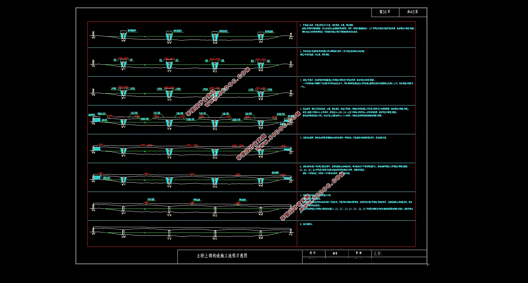
通过midas有限元软件建立连续箱梁桥模型对本桥上部结构进行计算分析,包括位移分析、内力分析、施工阶段内力验算、截面验算以及预应力筋估算等,另外还需要考虑温度荷载、混凝土收缩徐变、支座沉降和移动荷载方面的影响。对于下部结构,本设计采用手算的方式验算桥台、桩的承载能力。
经过严格地分析计算,本设计中的连续箱梁结构计算过程严谨,内力分布满足要求,符合相关规范的规定。
关键词:连续箱梁桥;有限元建模分析;应力验算;预应力钢束;钻孔灌注桩
Abstract
The title of this graduation project is the design of Qiyang Ring Road Overpass over the Yangtze River. The upper and lower structures of the main part of the bridge are designed and calculated, and the construction drawings are drawn.
According to the requirements of relevant codes, the detailed dimensions of the main girder, main pier and foundation pile are worked out in this design. The cross section of the main girder is single box and single chamber. The height of the box girder and the thickness of the bottom slab are changed by quadratic parabola. The web is changed by straight line at the end of No. 4 beam, and the thickness of the top slab remains unchanged. Considering the structure and geological conditions of continuous box girder bridge, bored cast-in-place piles are designed according to friction piles.
The model of continuous box girder bridge is established by Midas finite element software to calculate and analyze the superstructure of the bridge, including displacement analysis, internal force analysis, internal force checking in construction stage, section checking and prestressing tendon estimation, etc. In addition, the influence of temperature load, concrete shrinkage and creep, bearing settlement and moving load should also be considered. For the lower structure, the bearing capacity of abutment and pile is checked by hand calculation.
After rigorous analysis and calculation, the calculation process of the continuous box girder structure in this design is rigorous, the internal force distribution meets the requirements and meets the requirements of relevant specifications
Key words:Continuous box girder bridge;Finite element modeling and analysis;Stress checking calculation;Prestressed steel bundle; Bored cast-in-place pile
工程介绍
祁阳大道又名G322线祁阳绕城公路,起于祁阳城区北长虹街道办事处东风村,南止于祁阳城区浯溪街道办事处祁阳汽车南站(三南路口),全长11公里,是祁阳市区最重要的南北向城市主干道。
桥梁跨径组合为:34.44+60×3+42.83m。全桥为现浇预应力变截面混凝土连续箱梁。
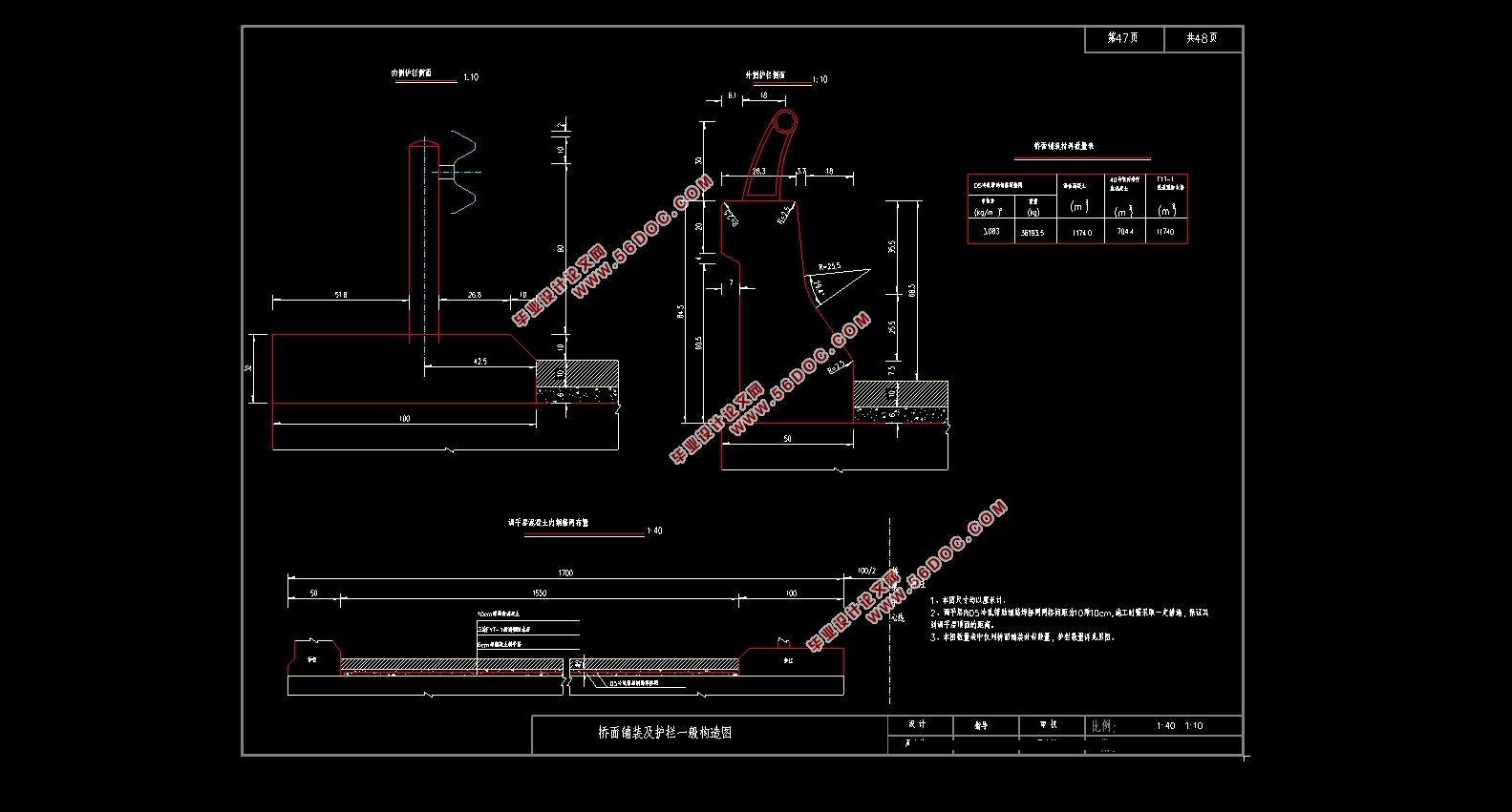
桥梁宽度为17m,采用整幅设置,内侧设置波型护栏,外侧设置防撞护栏,其布置为:B= 0.5m(外侧护栏)+0.5m(侧向净宽)+3.75(机动车道)×4+1m(内侧护栏)=17m。
1.1.2地形地貌
拟建桥梁位于祁阳县沿江路,地势平坦,原始地貌单元属湘江阶地地貌,现地形为祁阳大道,地面标高95.47~97.44m。区内交通发达,附近有国道G322、省道S320及众多市政公路经过,交通便利。

目录
摘要 I
Abstract II
第1章概述 1
1.1工程概况 1
1.1.1工程介绍 1
1.1.2地形地貌 1
1.1.3地质情况 1
1.2设计资料及基本数据 2
1.2.1技术标准 2
1.2.2材料及其设计参数 2
1.2.3设计依据 4
1.3桥型布置 4
1.3.1变截面连续箱梁的优点 4
1.3.2主桥结构尺寸 5
1.3.3桥面的铺装 7
1.3.4全桥结构单元的划分 7
1.4全桥施工阶段的划分 7
1.4.1主桥的施工方法 7
1.4.2全桥梁段的划分 8
1.4.3全桥施工工程的划分 8
第2章行车道板计算 9
2.1基本信息 9
2.2桥面板的计算 9
2.3悬臂板的计算 13
2.3.1恒载内力的计算 13
2.3.2活载内力的计算 13
2.3.3内力组合 14
2.4桥面板的配筋 15
2.4.1支点处配筋 15
2.4.2跨中处配筋 15
2.4.3抗剪验算 16
第3章主梁内力计算 17
3.1恒载内力的计算 17
3.2施工阶段内力计算 28
3.3活载内力计算 30
3.4活次内力计算 36
3.4.1温度次内力的计算 36
3.4.2基础变位影响力计算 39
3.4.3预加力产生的次内力计算 46
3.4.4徐变引起的次内力计算 49
3.5主梁作用效应组合 53
3.5.1承载能力极限状态的内力组合 53
3.5.2正常使用极限状态的内力组合 56
第4章配筋计算 61
4.1预应力钢束的估算 61
4.2预应力钢束的布置 66
4.3钢束预应力损失 66
4.3.1预应力钢筋与管道之间的摩擦引起的应力损失 67
4.3.2锚具变形、钢筋回缩和接缝压缩引起的应力损失 67
4.3.3混凝土弹性压缩引起的应力损失 67
4.3.4钢筋松弛引起的应力损失 68
4.3.5混凝土收缩和徐变引起的应力损失 68
4.4预应力损失计算结果 69
第5章主要截面验算 76
5.1控制截面的选择 76
5.2截面强度验算 76
5.2.1正截面抗弯验算 76
5.2.2斜截面抗剪验算 78
5.3正常使用极限状态截面验算 80
5.3.1使用阶段正截面抗裂验算 80
5.3.2使用阶段斜截面抗裂验算 82
5.3.3挠度验算 83
5.4持久状况和短暂状况构件的应力验算 84
5.4.1使用阶段正截面压应力验算 84
5.4.2使用阶段斜截面主压应力验算 86
5.4.3施工阶段正截面法向应力验算 87
5.4.4受拉区钢筋的拉应力验算 88
第6章局部承压验算 91
6.1局部承压尺寸要求 91
6.2局部抗压承载力计算 92
第7章桥墩墩柱计算 94
7.1荷载计算 94
7.1.1轴向力计算 94
7.1.2弯矩的计算 95
7.2截面配筋计算 95
7.2.1大、小偏心受压的判定 95
7.2.2计算纵向钢筋面积 95
7.3墩柱截面承载力复核 96
第8章钻孔灌注桩计算 98
8.1荷载设计 98
8.2桩长计算 99
8.3桩的内力及位移计算 100
8.3.1宽度的确定 100
8.3.2桩的变形系数的确定 100
8.3.3作用在桩上的外力 101
8.3.4计算最大冲刷下以下桩截面的弯矩及水平应力 101
8.3.5计算桩顶纵向水平位移 102
8.4桩基的配筋计算和桩身材料截面强度的验算 103
8.4.1桩身的最大弯矩及位置 103
8.4.2桩身截面强度的验算 103
总结 107
参考文献 108
致谢 109
|


