预应力混凝土(65+120+65)m连续刚构箱梁桥上部结构设计(含CAD图)(任务书,开题报告,外文翻译,论文说明书22000字,CAD图12张)
摘 要
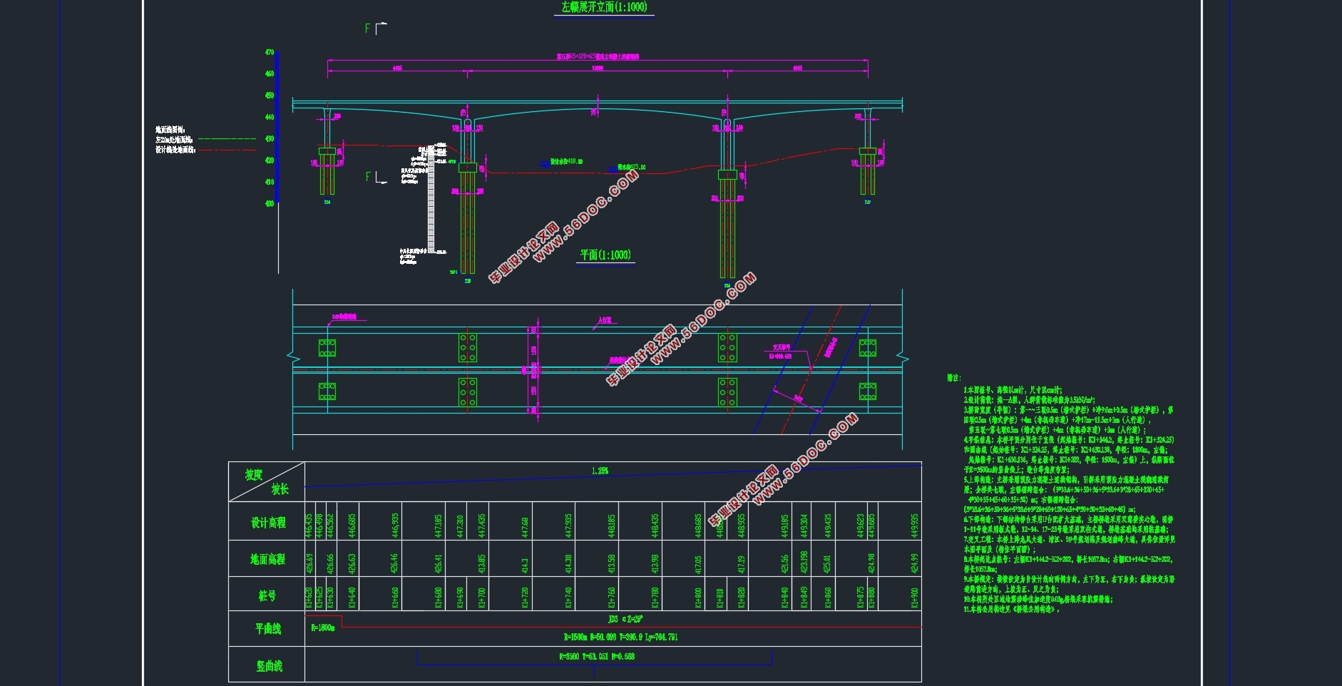
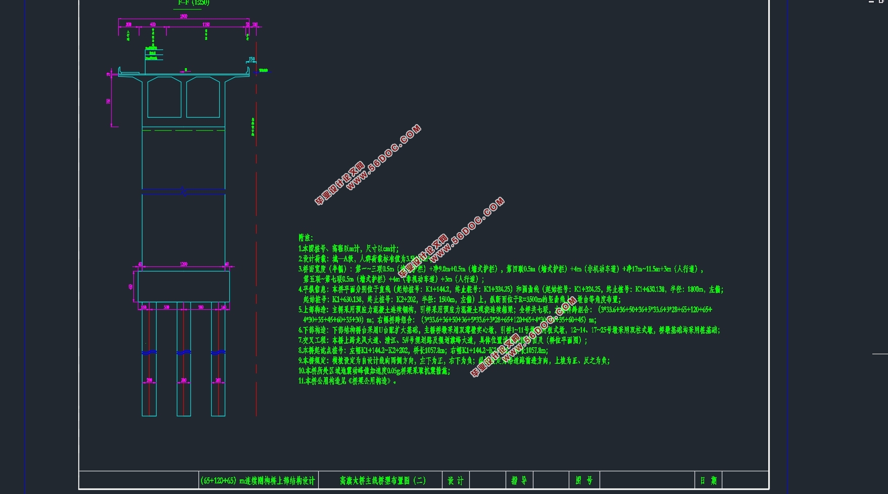
本设计为高旗大桥主桥部分即(65+120+65)m预应力混凝土连续刚构箱梁桥的上部结构设计。桥梁断面形式为单箱双室截面,顶宽19.00m,底宽12.00m。箱梁混凝土材料为C50混凝土。箱梁主墩墩顶处梁高7.50m,跨中最小梁高为2.50m,按1.8次抛物线变化。桥墩采用双薄壁板式墩。主梁采用挂篮悬臂现浇施工方法,每段梁高变化段分为14个模块施工,先边跨合拢,再中跨合拢。结构为全预应力混凝土构件。
使用Midas Civil软件建立桥梁结构模型,用PSC设计进行预应力钢筋的估算和设计,并进行施工阶段应力分析以及成桥阶段的截面验算及变形验算。对预应力、收缩徐变、温度、基础不均匀沉降的次内力进行分析,并按规范进行最不利荷载组合,对不同的结构体系、不同工况进行了全过程结构分析。桥梁模型设计成功、通过验算后,要绘制桥型立面、平面布置图;主梁一般构造图;主梁预应力钢筋布置图;主梁普通钢筋布置图,并编制完成设计计算说明书。
关键词:连续刚构桥;悬臂施工法;预应力钢筋;内力计算;设计验算
Abstract
This design is the superstructure design of the main bridge part of the Gaoqi Bridge, I. e., the prestressing concrete continuous steel box girder bridge with prestressing force of 65 120 65 m. The cross section of the bridge is single box and double chamber section, the top width is 19.00m, and the bottom width is 12.00m. Box girder concrete material for C 50 concrete. The beam height at the top of the main pier of box girder is 7.50 m, and the minimum beam height in the span is 2.50 m, varying according to the parabola of 1.8 times. The bridge pier adopts double thin-wall plate pier. The main beam is constructed by hanging basket cantilever cast-in-place construction method. Each section of beam height variation section is divided into 14 modules, the first side span is closed, then the middle span is closed. The structure is a fully prestressed concrete member.
The Midas Civil software is used to build the bridge structure model, the PSC design is used to estimate and design the prestressed steel bar, and the stress analysis in the construction stage, the cross-section checking calculation and the deformation checking calculation in the completion stage are carried out. The secondary internal forces of prestress, shrinkage, creep, temperature and uneven settlement of foundation are analyzed, and the most unfavorable load combination is carried out according to the code, and the whole process structure analysis is carried out for different structural systems and different working conditions. The bridge model has been successfully designed. After checking calculation, we should draw the bridge elevation, plane layout plan; main beam general structure map; main beam prestressed steel bar layout plan; main beam common steel bar layout plan, and compileComplete the design calculation specification.
Key Words:Continuous rigid frame bridge; cantilever construction method; prestressed steel bar; internal force calculation; design checking calculation
设计标准
(1)设计车速为60Km/h;
(2)设计荷载为公路-Ⅰ级;
(3)设计洪水频率是1/100;
(4)桥梁的标准断面布置形式为:
3m(人行道+栏杆)+3.5m(非机动车道)+0.5m(隔离带)+11.5m(机动车道)+0.5m(护栏)+2m+0.5m(护栏)+11.5m(机动车道)+0.5m(隔离带)+3.5m(非机动车道)+3m(人行道+栏杆)=40m;
(5)桥梁截面形式:单箱双室;
(6)环境类别为Ⅰ类;
(7)结构物安全等级为公路-Ⅰ级。

目 录
摘 要 I
Abstract II
目 录 III
第1章 绪论 2
1.1 预应力混凝土连续刚构桥 2
1.1.1 发展历程 2
1.1.2 结构和受力特点 3
1.2 地质条件 3
1.3 技术标准及采用规范 4
1.3.1 设计标准 4
1.3.2 主要技术标准及规范 4
1.4 施工方法 4
1.4.1 主要施工方法 4
1.4.2 施工注意事项 5
第2章 桥跨总体布置及结构主要尺寸 6
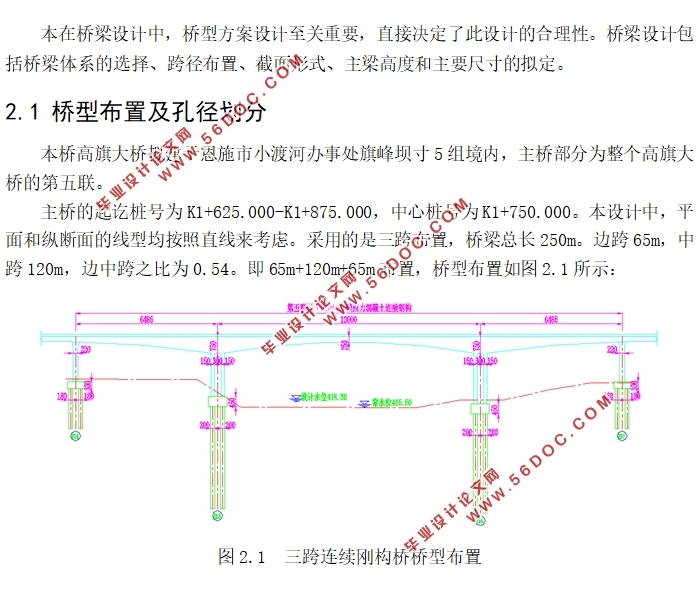
2.1 桥型布置及孔径划分 6
2.2 上部结构尺寸拟定 6
2.2.1梁高尺寸拟定 7
2.2.2 横截面尺寸拟定 7
2.2.4 横隔板 8
2.3 下部结构尺寸拟定 8
2.4 主要材料 8
2.4.1 混凝土 8
2.4.2 预应力材料 9
2.4.3 钢材 10
2.4.4 其他材料 10
2.5 全桥施工节段划分 11
2.6 施工阶段划分 12
2.7 毛截面几何特性 14
第3章 荷载内力计算 16
3.1 Midas Civil软件简介 16
3.2 桥梁结构模型的建立 16
3.2.1 结构模型的单元划分 16
3.2.2 边界条件 17
3.2.3 荷载信息 19
3.3 恒载内力计算 20
3.3.1 施工阶段内力计算 20
3.3.2 成桥阶段内力计算 24
3.4 活载内力计算 25
第4章 预应力钢束的估算与布置 29
4.1预应力钢束的估算 29
4.2 预应力钢束的布置 30
4.2.1 纵向预应力钢束的布置 32
4.2.2 竖向预应力钢束的布置 34
4.2.3横向预应力钢束的布置 35
4.3 预应力损失计算 35
4.3.1 预应力筋与管道壁之间的摩擦引起的应力损失σl1 36
4.3.2 锚具变形、钢筋回缩和接缝压缩引起的应力损失σl2 36
4.3.3 混凝土的弹性压缩引起的应力损失σl4 36
4.3.4 预应力钢筋的松弛引起的应力损失σl5 37
4.3.5 混凝土的收缩和徐变引起的应力损失σl6 37
4.4 有效预应力计算 38
第5章 结构次内力计算及内力组合 40
5.1 预应力次内力 40
5.2 收缩次内力 42
5.3 徐变次内力 43
5.4 温度次内力 45
5.5 基础不均匀沉降次内力 49
5.6 荷载组合 51
5.6.1 承载能力极限状态作用效应组合 52
5.6.2 正常使用极限状态作用效应组合 53
第6章 截面验算 59
6.1 持久状况正常使用极限状态计算及验算 59
6.1.1 正截面抗裂验算 59
6.1.2 斜截面抗裂验算 60
6.1.3 挠度验算 60
6.2 持久状况和短暂状况构件的应力计算及验算 62
6.2.1 持久状况状况构件的应力计算及验算 62
6.2.2 短暂状况构件的应力计算及验算 66
6.3 持久状况承载能力极限状态验算 67
参考文献 69
致 谢 71
|