6×30m预应力混凝土连续箱梁桥施工图设计(含CAD图)(任务书,开题报告,论文说明书24000字,CAD图10张)
摘要
预应力混凝土连续梁桥具有结构受力性能好、变形小、造型简洁美观,并且后期养护工作量少的特点,跟普通的混凝土构件相比,它具有抗裂能力强、抗渗性能好、刚度大、强度高、抗剪能力和抗疲劳性能好的优点,所以预应力混凝土连续梁桥的应用更为广泛。
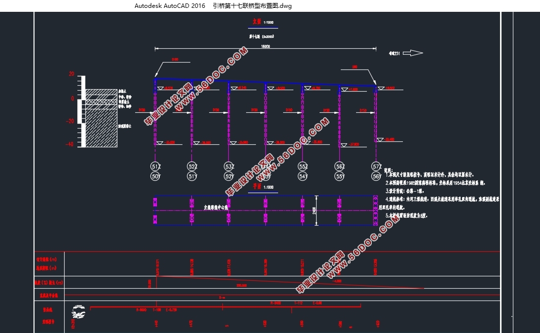
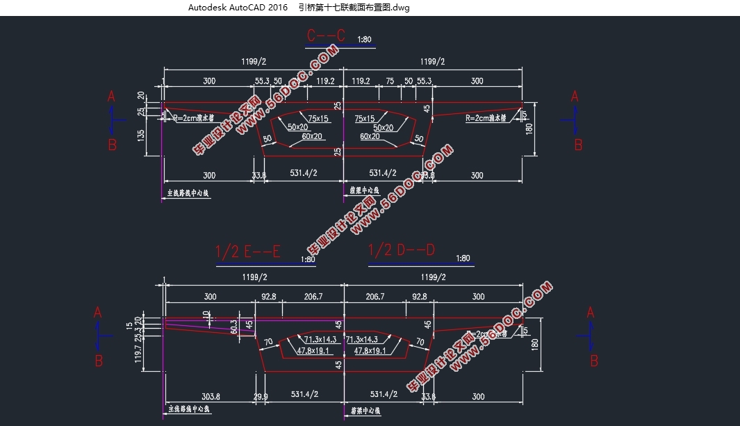
本次设计为广东潮州大桥第十七联引桥施工图设计,根据桥梁设计的一般原则,将本桥设计为6×30m的预应力混凝土连续箱梁桥,梁宽为12m,梁高为1.8m箱型,截面采用单箱单室的等截面形式,全桥采用满堂支架分节段现浇施工法。
本次设计内容包括上部结构、下部结构的设计和计算;上部结构运用MIDAS/CIVIL2015软件进行设计和验算,下部结构采用手算的方式进行设计和验算;根据任务书中的要求,上部结构内容包括结构尺寸的拟定及几何特性计算、作用效应组合计算、配筋设计及布置、承载力及正常使用状态计算、预应力损失计算和对设计的主梁进行验算;下部结构内容包括墩台、承台和桩基的设计与计算。
设计过程中参考了很多推荐的设计规范,也借鉴和引用了一些优秀的桥梁设计模板。同时通过采用MIDAS软件来模拟桥梁施工阶段的受力分析,与手算相比极大地节约了时间,并且提高了计算数据的精确度。最终在指导老师的耐心指导与帮助下,我的毕业设计进行得很顺利,做到了图文并茂,而且所有计算结果均满足要求,在此对设计界的前辈及指导老师表示衷心的感谢!
关键词:预应力混凝土连续箱梁桥;分节段现浇施工;上部结构;下部结构;设计和验算。
Abstract
Prestressed concrete continuous girder bridge has the characteristics of good structural performance, small deformation, simple and beautiful shape, and low post-maintenance work. Compared with ordinary concrete, it has strong anti-cracking ability, good impermeability, Large, high strength, shear capacity and good resistance to fatigue, so the application of prestressed concrete continuous beam bridge is more extensive.
Based on the general principle of bridge design, the bridge is designed as a 6 × 30m prestressed concrete continuous box girder bridge with a single cross section of a single box and a single section of a single chamber, which is designed for prestressed concrete continuous box girder bridge. Form, the beam width is 12m, the beam height is 1.8m, the full bridge adopts the full house bracket sub-section cast-in-place construction method.
This design includes the upper structure, the lower structure of the design and calculation; the upper structure of the use of MIDAS / CIVIL2015 software design and verification, the lower structure of the way to design and check the calculation; according to the requirements of the task book, the upper structure includes The calculation of the structural size and the calculation of the geometric characteristics, the calculation of the effect effect, the design and arrangement of the reinforcement, the bearing capacity and the normal use state, the calculation of the prestress loss and the checking of the main girder of the design. The lower structure includes the pier, And pile design and calculation.
The design process refers to a lot of related design specifications, but also draw on and cited some of the excellent design results. At the same time through the use of MIDAS software to calculate the internal force of the bridge structure, compared with the hand count greatly saves time. And finally in the guidance of the patient's guidance and help, my graduation design was very smooth, and all the results are met the requirements of the design industry's predecessors and instructors to express my heartfelt thanks!
keyword: Prestressed concrete continuous box girder bridge;sub - section cast - in - place construction;superstructure;lower structure;design and checking.
本设计为潮州大桥第十七联引桥施工图设计,该桥主梁为单箱单室的预应力混凝土结构,全桥梁高1.8m,梁宽为12m。该桥位于广东省潮州市,是组成广东潮州大桥主线桥的一部分。随着城市车流量的快速增加,建设潮州大桥意义重大,它对广东地区的经济发展起着重要的作用。
潮州大桥第十七联引桥起点里程桩号为K2+440.000,终点里程桩号为K2+620.000,该桥全长180m。本设计以安全为第一宗旨,并统筹兼顾造型优美、造价低廉、施工简便,而且对环境的影响尽可能的降低。

目 录
1 绪 论 1
1.1 工程背景 1
1.2 地质资料及技术标准 2
1.2.1 工程地质资料 2
1.2.2 主要技术指标 2
1.2.3 设计规范 2
1.3 桥式方案的选择 2
1.3.1 设计原则 2
1.3.2 方案比选 3
1.4 预应力混凝土连续梁桥的概述 3
1.5 毕业设计的目的及意义 4
1.5.1 毕业设计的目的 4
1.5.2 毕业设计的意义 4
2 结构初步设计 5
2.1 设计概述 5
2.2 截面尺寸拟定 6
2.2.1 等截面箱梁形式 6
2.2.2 主梁高度 6
2.2.3 顶底板厚度 6
2.2.4 腹板厚度 6
2.2.5 梗腋(承托) 6
2.3 施工方法 7
2.3.1 施工阶段 7
2.3.2 施工注意事项 7
3 Midas civil建模及主梁内力计算 8
3.1 建模过程 8
3.1.1 设定建模操作环境 8
3.1.2 定义材料 8
3.1.3 定义截面 8
3.1.4 建立梁单元有限元模型 9
3.1.5 定义时间依存性材料 9
3.1.6 定义边界条件 9
3.1.7 建立静力荷载工况 9
3.1.8 移动荷载工况的定义 10
3.1.9 定义施工阶段信息 10
3.2.1 生成荷载组合 10
3.2.2 恒载内力计算 11
3.2.3 活载内力计算 14
3.2.4 内力组合 16
4 预应力钢束的估算与布置 20
4.1 预应力钢束面积的估算 20
4.2 预应力钢束估算结果 22
4.3 钢束的布置 23
4.3.1 钢束布置构造要求 23
4.3.2 钢束布置原则 24
4.3.3 钢筋起弯角和线型的确定 24
5 普通钢筋的估算与布置 32
5.1 普通钢筋面积的估算 32
5.2 普通钢筋的布置 34
6 预应力损失计算 39
6.1 基本理论 39
6.2 预应力损失计算 39
6.2.1 预应力钢筋与管道之间摩擦引起的应力损失 39
6.2.2 锚具变形、钢筋回缩和接缝压缩引起的应力损失 39
6.2.3 混凝土弹性压缩引起的应力损失 40
6.2.4 钢筋松弛引起的应力损失 40
6.2.5 混凝土收缩和徐变引起的应力损失 40
6.2.6 截面预应力损失合计和有效预应力计算 41
6.3 预应力损失结果分析 41
7 截面验算 49
7.1 使用阶段正截面抗弯验算 49
7.2 使用阶段斜截面抗剪验算 50
7.3 使用阶段正截面抗裂验算 52
7.4 使用阶段斜截面抗裂验算 54
7.5 使用阶段斜截面主压应力验算 55
7.6 使用阶段正截面压应力验算 57
8 桥墩的设计与计算 59
8.1 桥墩的尺寸 59
8.2 墩帽的设计与计算 59
8.2.1 墩帽自重及内力计算 59
8.2.2 截面配筋计算 60
8.3 墩柱的设计和计算 62
8.3.1 荷载计算 62
8.3.2 截面配筋计算 64
8.3.3 截面承载力复核 64
9 钻孔灌注桩与承台的设计 67
9.1 荷载计算 67
9.2 桩长计算 67
9.3 桩的内力及位移计算 69
9.3.1 桩的计算宽度 69
9.3.2 桩的变形系数 70
9.3.3 桩顶刚度系数 值的计算 70
9.3.4 计算承台底面原点0处位移 71
9.3.5 计算作用在每根桩顶上的作用力 72
9.3.6 计算最大冲刷线处桩身弯矩 ,水平力 及轴向力 72
9.3.7 桩身最大弯矩位置及弯矩计算 72
9.3.8 计算最大冲刷线以下深度 处桩截面上的弯矩 及水平压应力 73
9.3.9 桩顶纵向水平位移验算 74
9.3.10 桩身截面配筋计算 75
9.4 承台的设计 77
9.4.1 桩顶局部受压验算 77
9.4.2 承台受冲切承载力验算 77
9.4.3 受剪切承载力验算 78
9.4.4 承台受弯承载力验算 79
10 桥台的设计与计算 81
10.1 桥台的类型和主要材料 81
10.2 桥台一般构造尺寸的规定 81
10.3 台帽计算 81
10.3.1 荷载计算 81
10.3.2 内力计算及截面验算 81
设计总结 83
参考文献 84
致 谢 85
|