3×25m预应力混凝土连续梁桥的设计与计算(含CAD图,Midas模型)(任务书,开题报告,研究综述,论文说明书20000字,CAD图8张,Midas模型)
摘 要
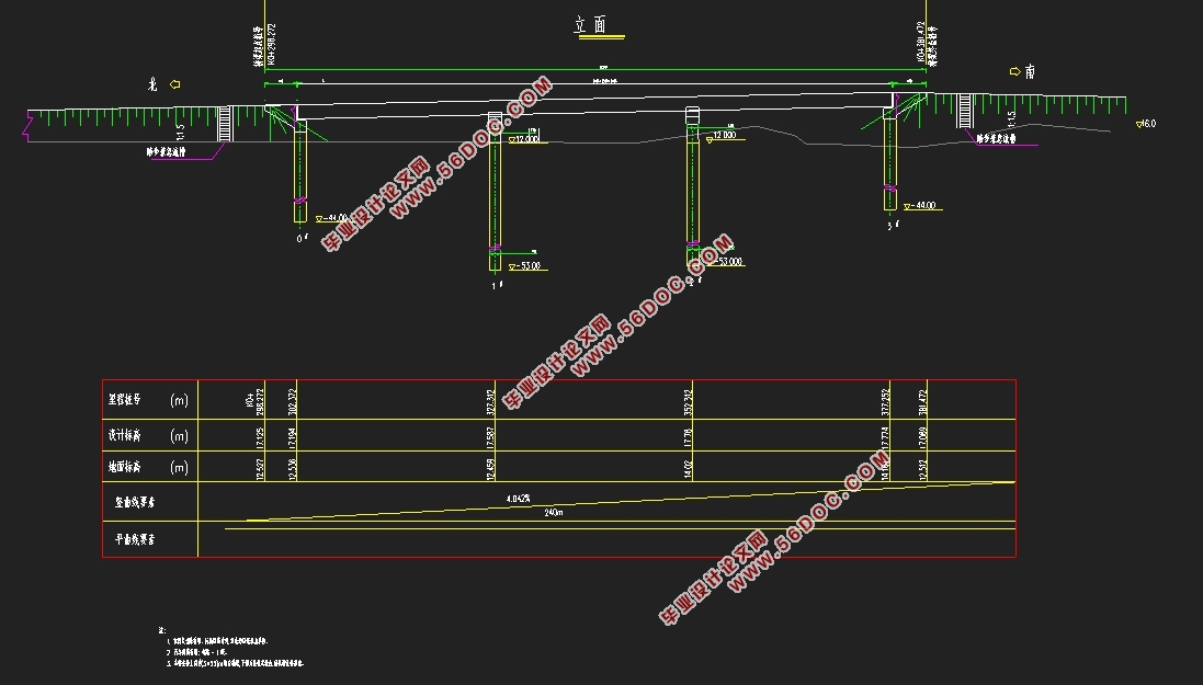
本次毕业设计为三跨预应力混凝土连续梁桥,总跨径为75m,桥面宽度为8m,桥面横坡采用1.5%,单向双车道,汽车荷载等级为公路-Ⅰ级。依据任务书要求和相关规范资料确定桥型、截面形式和施工方法,并确定混凝土和筋材特性值,同时应用 Midas civil有限元软件根据桥梁各部分尺寸拟定建立桥梁基本模型和钢筋束配置,并进行相关结构内力分析,在进行结构内力分析时,需要考虑混凝土收缩徐变、温度、支座等次内力的影响,还需要进行计算配筋结果的验算。
本设计主要是对预应力混凝土连续梁桥的上部结构进行设计,设计中主要进行了桥梁桥型的总体布置及结构截面尺寸拟定、桥梁各种荷载内力计算、桥梁的预应力钢束的估算与布置、桥梁预内力计算与应力损失和有效应力的验算、次内力的验算、内力组合验算以及主梁截面强度验算等计算与验算分析。最后用AUTOCAD软件绘制预应力混凝土连续梁结构设计的主要构造图、预应力束布置图及施工顺序图。
关键词:预应力连续梁桥 Midas(civil) 建模 结构内力分析 验算
Design and calculation of 3×25m prestressed concrete continuous girder bridge
Abstract
This graduation project is a three-span prestressed concrete continuous girder bridge.The total span is 75m, the bridge deck width is 8m, the bridge deck cross slope adopts 1.5%, one-way double lane, and the vehicle load grade is highway-I grade.Determining bridge type, section form and construction method according to the requirements of the task book and relevant normative data.And determine the characteristic values of concrete and reinforced materials, and use Midas civil finite element software to establish the basic model of the bridge and the bundle configuration according to the dimensions of each part of the bridge.The internal force analysis of the relevant structure is carried out. In the analysis of the internal force of the structure, it is necessary to consider the influence of the secondary internal force such as the shrinkage and creep of the concrete, the temperature and the support, and the calculation of the results of the reinforcement is also required.
This design is mainly for the design of the superstructure of prestressed concrete continuous girder bridge. In the design, the overall layout of the bridge type and the dimension of the structure are proposed, the internal force calculation of various loads of the bridge, and the prestressed steel bundle of the bridge are estimated. Arrangement, bridge pre-internal force calculation and stress loss and effective stress check, sub-internal force check, internal force combination check and main beam section strength check calculation and calculation analysis. Finally, the main structural drawing, prestressed beam layout drawing and construction sequence diagram of the prestressed concrete continuous beam structure design are drawn by AUTOCAD software.
Key Words: Prestressed continuous beam bridge;Midas(civil);Modeling;Structural internal force analysis;Check calculation
1.1 工程概况
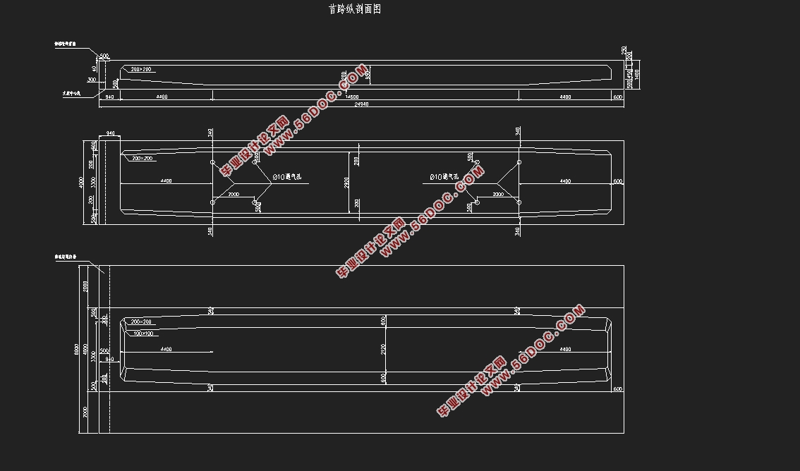
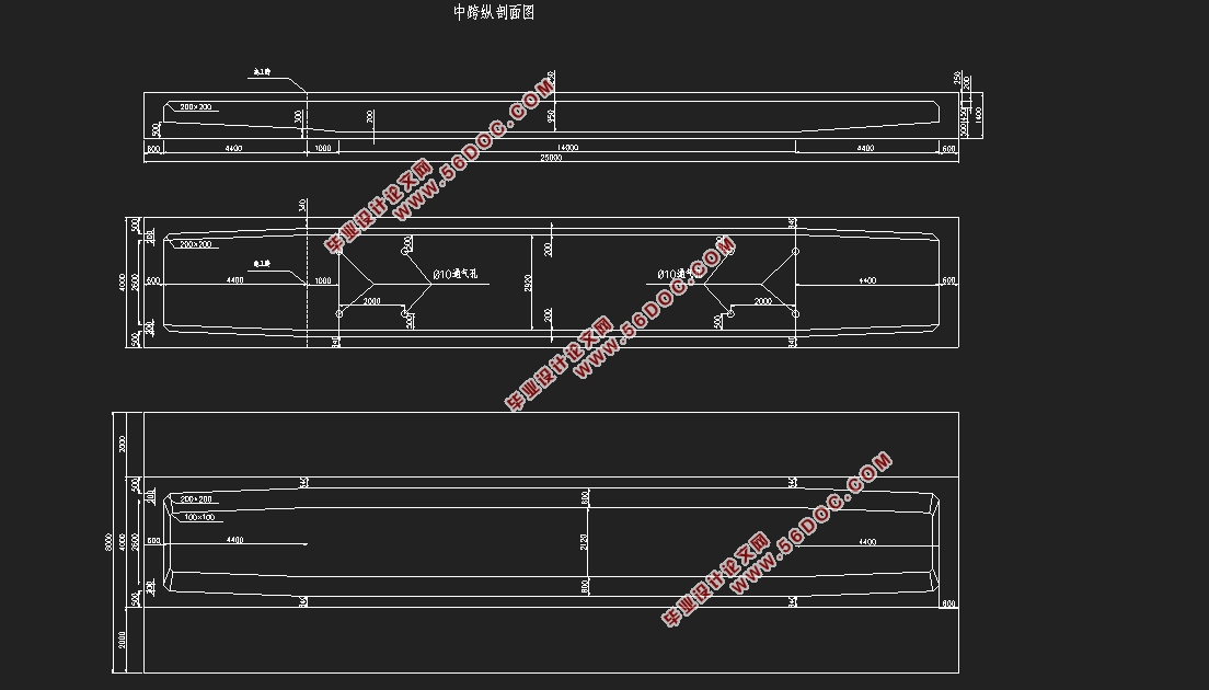
本次毕业设计采用预应力混凝土连续箱梁结构,总跨径为75m,计算跨径为25m,采用单向双车道,桥面宽度8m(0.5m护栏+2×3.5m机动车道+0.5m护栏),截面形式为单箱单室箱形截面。汽车荷载等级为公路-Ⅰ级,边支座和中支座的支座位移都为下沉5mm。温度影响参照《公路桥涵设计通用规范》(JTG D60-2004)中4.3.10中第三条考虑。
1.2 设计基本资料
1.2.1 主要技术指标
(1)总跨径:75m;计算跨径:25m,标准跨径:24.94m+25m+24.94m;
(2)桥梁宽度:0.5m护栏+2×3.5m机动车道+0.5m护栏,共8m;
(3)汽车荷载:公路-Ⅰ级;
(4)每侧护栏重量按6kN/m计,混凝土考虑10年的收缩徐变,整体温度均按20℃考虑。

目 录
第一章 概述 1
1.1 工程概况 1
1.2 设计基本资料 1
1.2.1 主要技术指标 1
1.2.2 材料及特性 1
1.2.3 设计荷载 2
1.2.4 桥面铺装 2
1.2.5 温度作用 3
1.2.6 施工方式 3
1.2.7 设计依据 3
第一章 桥型及纵横断面布置 4
2.1 桥型布置 4
2.2 截面形式及截面尺寸拟定 4
2.2.1 截面形式 4
2.2.2 梁高拟定 4
2.2.1 细部尺寸拟定 5
2.3 横截面构造图 6
第二章 结构有限元建模 8
3.1 节点建立和单元划分 8
3.2 材料定义 9
3.3 截面定义 10
3.4 边界条件定义 10
3.5 施工阶段定义 11
3.6 成桥阶段 11
3.6.1 车辆荷载 11
3.6.2 温度荷载 11
3.7 荷载组合 12
3.7.1 荷载工况说明 12
3.7.2 荷载组合说明 12
第三章 主梁内力计算 14
4.1 恒载内力计算 14
4.1.1 自重 14
4.1.2 二期恒载 14
4.1.3 自重内力包络图 15
4.1.4 恒载内力包络图 17
4.2 活载内力计算 18
4.2.1 汽车荷载 18
4.2.2 温度荷载 21
4.2.3 支座沉降荷载 24
4.3 作用组合效应 24
4.3.1 承载能力极限状态计算时作用效应组合 24
4.3.2 正常使用极限状态计算时作用效应组合 26
第四章 预应力钢束估算和布置 28
5.1钢筋束布置原则 28
5.1.1 纵向预应力钢束受力特点 28
5.1.2 纵向预应力钢束布置原则 28
5.2 预应力钢束的估算 29
(1) 按承载能力极限计算时满足正截面强度要求: 29
5.3 钢筋特性及主要钢筋布置情况 33
5.3.1 钢束特性值 33
5.3.2 钢束布置图 34
5.4 预应力损失计算 39
5.4.1控制应力 39
5.4.2各项预应力损失及计算原则 40
5.4.3 有效预应力 40
5.4.4 钢束预应力损失图 40
第六章 主梁截面验算(PSC设计) 42
6.1 施工阶段法向压应力验算 42
6.1.1 计算依据 42
6.1.2 验算结果 42
6.1.3 验算注释 47
6.2 受拉区钢筋的拉应力验算 47
6.2.1 计算依据 47
6.2.2 验算结果 48
6.2.3 验算注释 50
6.3 使用阶段正截面抗裂验算 50
6.3.1 计算依据 50
6.3.2 验算结果 51
6.3.3 验算注释及结论 54
6.4 使用阶段斜截面抗裂验算 54
6.4.1 计算依据 54
6.4.2 验算结果 55
6.4.3 验算注释及结论 59
6.5 使用阶段正截面压应力验算 59
6.5.1 计算依据 59
6.5.2 验算结果 60
6.5.3 验算注释及结论 62
6.6 使用阶段斜截面主压应力验算 62
6.6.1 计算依据 62
6.6.2 验算结果 63
6.6.3 验算注释及结论 72
6.7 使用阶段正截面抗弯验算 72
6.7.1 计算依据 72
6.7.2 验算结果 74
6.7.3 验算注释及结论 77
6.8 使用阶段斜截面抗剪验算 77
6.8.1 计算依据 77
6.8.2 验算结果 79
6.8.3 验算注释及结论 82
总结与回顾 84
致 谢 85
参考文献 86
|