金东路大桥主桥预应力混凝土连续梁桥设计(48m+80m+48m)(含CAD图)(任务书,开题报告,论文说明书20000字,CAD图14张)
摘 要
预应力混凝土连续梁桥是工程上广泛使用的一种桥型,它不但具有可靠的强度、抗震能力、刚度及抗裂性,而且具有行车舒适平稳、养护工作量小、伸缩缝少、 造型简洁美观、设计及施工经验成熟等特点。
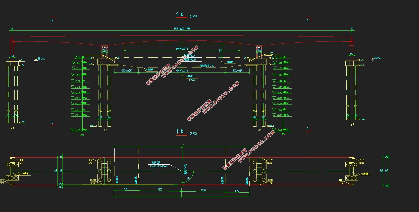
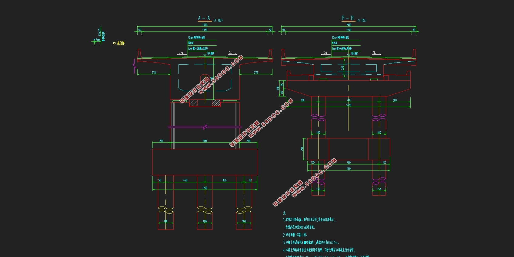
该设计针对桥址处地形地质条件,从桥跨布设及施工方法等多方面进行综合比较,同时充分考虑设计参数和环境影响,选择了210m三跨变截面预应力混凝土箱形连续梁桥,按照“安全、适用、经济、美观”的原则。采用双向6车道,桥宽为26m,由两个单箱单室截面组成;梁高采用变高度梁, 按二次抛物线变化,边跨支点处梁高2.5m、跨中处梁高2.5m、中跨支点处梁高5.0m,采用满堂支架施工。
设计计算时,首先利用结构力学求解器进行恒载内力计算、利用《公路钢筋混凝土及预应力混凝土桥涵设计规范》和Midas Civil 2015进行活载内力计算(其中横向分布系数采用偏载增大系数乘以车辆折减系数)、Midas Civil 2015进行次内力(基础沉降、温差应力)的计算,在此基础上按承载能力极限状态和正常使用极限状态进行荷载效应组合,并绘制弯矩和剪力包络图;其次,该设计按照全预应力构件设计,根据正截面抗裂要求,确定预应力钢筋的数量,按照钢筋束布置构造要求和布置原则进行钢筋束的配置,并依据后张法进行预应力损失和有效预应力的计算;再者,对上部结构进行正截面抗弯承载力、斜截面抗剪承载力、正截面抗裂、混凝土法向应力及挠度验算,最后根据《公路桥涵地基与基础设计规范》(JTG D63-2012)进行桥墩设计和竖向承载力、水平承载力验算和桩基础设计。该设计完成了桥梁上部结构、下部结构的设计和验算,并编制了计算书和相关图纸。
计算结果表明该桥在正常使用极限状态及承载能力极限状态下,桥梁结构各主要受力构件强度、刚度及变形均满足规范要求。
关键词:预应力混凝土 连续梁桥 箱梁 悬臂施工
Abstract
Prestressed concrete continuous beam bridge is a bridge engineering widely used, it not only has a reliable strength, shock resistance, stiffness and crack resistance, and has a smooth driving comfort, small conservation work, fewer joints, simple shapes beautiful, mature experience in design and construction features.
The design for topographic and geologic conditions at the bridge site, across from the bridge layout and construction methods and other aspects of comprehensive comparison, taking full account of the environmental impact of the design parameters and select the 210m three-span Prestressed concrete box girder bridge, according to the principle of "security, application, economic, aesthetic," the. Two-way 6 lanes, the bridge width of 26m, consisting of two single box single cross-sectional configuration; high beam with variable height of the beam, according to parabola change, at the fulcrum side span beam height 2.5m, at the mid-span girder high 2.5m, cross at the fulcrum of the beam height 5.0m.
Design calculations, the first structural mechanics solver constant load internal force calculation, using the "highway reinforced concrete and prestressed concrete bridge design specifications" and Midas Civil Trial perform Live Load Calculation (which uses partial load transverse distribution coefficient increases Multiplier in vehicle reduction factor), Midas Civil Trial were secondary internal forces (foundation settlement, temperature stress) calculation on this basis, according to the carrying capacity limit state and serviceability limit state load effect combinations, and draws moment and shear pack network diagram; secondly, the design according to the design of the full prestressing member, according to the requirements of normal section crack resistance, determine the number of prestressing steel, configure tendons tendons arranged in accordance with structural requirements and layout principles, and based on pre-post-tensioned effective prestress loss and stress calculations; Furthermore, the structure of the upper part of flexural Strength, shear Strength, normal section crack resistance of concrete normal stress and deflection checking, Finally, according to "foundation and highway bridges and culverts foundation design specification "(JTJ 024-85) were piers and vertical design capacity, the level of Bearing Capacity and pile foundation design. The design is completed the bridge superstructure, the substructure design and checking, and the preparation of calculations and related drawings.
The results show that the bridge in the limit state and ultimate limit state, the bridge structure of the main force component strength, stiffness and deformation can meet regulatory requirements.
Keywords: prestressed concrete ,box girder ,continuous beam bridge, construction Full Support
1.1.1标准跨径
金东路大桥全长176m,按照设计任务书中的要求,本联设计采用变截面连续箱梁结构形式。为了在整体上保证桥的整体协调及美观性,跨径布置时,要和前后联协调好,通过计算调整,最终确定本联的跨径布置如下:48m+80m+48m= 176m
本联为三跨连续梁桥,三跨连续梁合理布置。由参考文献[1]第二章第一节(P69)可知,三跨连续梁合理的跨径布置为边跨与中跨之比为0.6:1到0.7:1之间,且对称布置,该桥选择的边跨与中跨比为0.6:1,并对称布置。

目 录
摘要……………………………………………………………………………………………I
Abstract …………………………………………………………………………………….....II
第一章 方案设计 ……………………………………………………………………………1
1.1 跨径布置……………………………………………………………………………….1
1.2 顺桥向设计…………………………………………………………………………….1
1.3 横桥向设计…………………………………………………………………………….1
第二章 恒载计算 ……………………………………………………………………………4
2.1 节段划分及截面几何要素计算……………………………………………………….4
2.2 一期恒载计算………………………………………………………………………….5
2.3 二期恒载计算………………………………………………………………………….5
2.4 总恒载效应…………………………………………………………………………….6
第三章 活载计算……………………………………………………………………………..8
3.1 汽车荷载 ……………………………………………………………………………...8
3.2 最大、最小弯矩计算 ………………………………………………………………..10
3.3 最大、最小剪力计算 ………………………………………………………………..12
第四章 次内力计算………………………………………………………………………….15
4.1 温度次内力计算 ……………………………………………………………………..15
4.2 支座沉降次内力计算 ………………………………………………………………..18
第五章 内力组合及内力包络图…………………………………………………………….19
5.1 频遇组合......... ………………………………………………………………………..19
5.2 准永久组合..... ………………………………………………………………………..21
5.3 基本组合 ……………………………………………………………………………..21
5.4 包络图 ………………………………………………………………………………..22
第六章 预应力筋的计算与布置…………………………………………………………….26
6.1 原理与方法 …………………………………………………………………………..26
6.2 预应力筋的配置 ……………………………………………………………………..26
6.3 钢束布置 ……………………………………………………………………………..26
第七章 净截面及换算截面几何特性计算………………………………………………….32
7.1 概述 …………………………………………………………………………………..32
7.2 净截面几何特性计算 ………………………………………………………………..32
7.3 换算截面性质计算 ........……………………………………………………………..35
第八章 预应力损失及有效预应力计算 ………………………………………………….37
8.1 控制应力及有关参数计算 …………………………………………………………..37
8.2 摩擦损失 ……………………………………………………………………………..37
8.3 锚具回缩损失 ………………………………………………………………………..49
8.4 弹性压缩损失 ………………………………………………………………………..61
8.5 应力松弛损失 ………………………………………………………………………..62
8.6 收缩徐变损失 ………………………………………………………………………..63
8.7 预应力损失组合及有效预应力计算 ………………………………………………..65
第九章 承载能力极限状态验算 ……………………………………………………………69
9.1 正截面承载能力验算………………………………………………………………….69
9.2 斜截面承载能力验算………………………………………………………………….74
第十章 正常使用极限状态验算 ……………………………………………………………78
10.1 抗裂验算 …………………………………………………………………………….78
第十一章 持久状况和短暂状况应力验算 …………………………………………………80
11.1 持久状况截面混凝土法向应力验算 ……………………………………………….81
11.2 短暂状况截面混凝土法向应力验算 ……………………………………………….82
第十二章 墩及桩基础设计与计算 …………………………………………………………85
12.1 支座 ………………………………………………………………………………….85
12.2 墩身设计与验算……………………………………………………………………...86
12.3 承台设计……………………………………………………………………………...88
12.4 桩基础设计…………………………………………………………………………...88
参考文献……………………………………………………………………………………....91
致谢…………………………………………………………………………………………....92
|