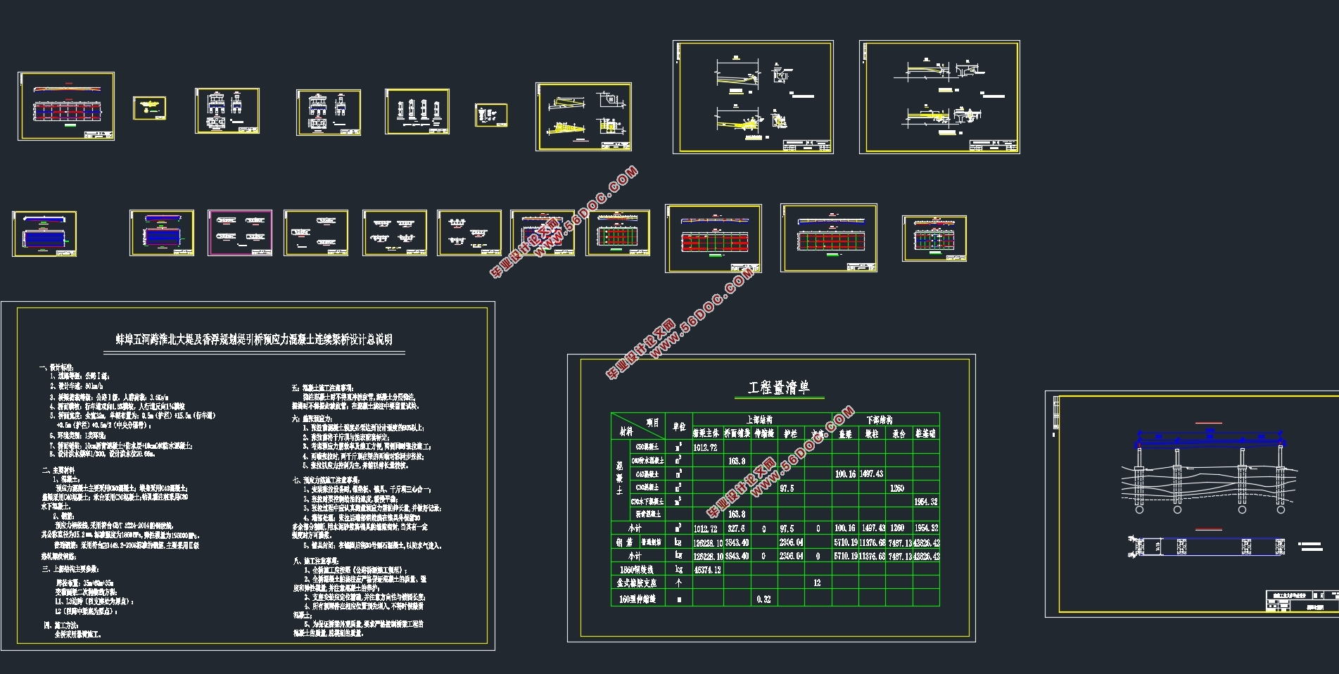
三跨35m+60m+35m预应力混凝土连续梁桥设计(含CAD图)(任务书,开题报告,论文计算书18000字,CAD图21张)
摘 要
预应力混凝土连续梁桥适用于跨径从30m到100m的中等跨度和大跨径的桥梁,其在结构重力和汽车荷载等恒、活载作用下,主梁受弯,跨中截面承受正弯矩。作为超静定结构,温度变化、混凝土收缩徐变、基础变位以及预加力等,均会使桥梁结构产生次内力。预应力结构不但具有可靠的强度,刚度及抗裂性,而且具有行车舒适平稳,养护工作量小,设计及施工经验成熟的特点。蚌埠五河跨淮北大堤及香浮规划堤引桥预应力混凝土连续梁桥是一座预应力连续梁桥,该桥采用单箱双室直腹板变截面箱型梁。跨径布置为35m+60m+35m三跨变截面连续梁桥。施工方式是满堂支架整体现浇。该设计首先根据桥梁手册和设计实例做出设计方案,接着对结构进行恒载、活载及次内力的计算;然后在内力计算的基础上进行荷载组合,并绘制弯矩和剪力包络图;接着做的是根据频遇组合初估预应力筋并布置预应力钢筋;再接着就是预应力损失及有效预应力的计算;最后是抗剪抗弯以及抗裂性的验算,验算结果均符合要求。本设计主要对上部结构进行了详细的计算,对下部结构和工程造价用量只进行了初步计算。
关键词: 结构设计 连续梁桥 满堂支架 预应力筋配置
Five rivers across Huaibei embankment and Xiangfu planning dike approach bridge
Design of Prestressed Concrete Continuous Beam Bridge
Abstract
Prestressed concrete continuous girder bridges are suitable for medium span and large span bridges with spans ranging from 30m to 100m. Under constant and live loads such as structural gravity and vehicle loads, the main beams are bent, and the mid-span cross-sections are subjected to positive bending. Moments. As a statically indeterminate structure, temperature changes, shrinkage and creep of concrete, foundational displacement, and pre-energization all result in secondary internal forces acting on the bridge structure. The prestressed structure not only has reliable strength, rigidity and crack resistance, but also has the characteristics of comfortable and stable running, small maintenance workload, mature design and construction experience. The prestressed concrete continuous girder bridge over the Huaibei embankment and Xiangfu planning embankment of the Wuhe River is a prestressed continuous girder bridge with single box double-compartment straight webs with variable section box girders. The span arrangement is a 35m+60m+35m three-span variable-span continuous girder bridge. The construction method is full cast in place. The design firstly makes a design proposal based on bridge manuals and design examples. Then the structure is subjected to constant load, live load, and sub-internal forces; then load combination is performed on the basis of internal force calculation, and the moment and shear envelope diagrams are plotted. The next step is to pre-assess the prestressing tendons and arrange the prestressed reinforcements according to the frequency combination; then the calculation of the prestress loss and the effective prestress; and finally the verification of the shear resistance and the crack resistance, and the checking results are in accordance with Claim. This design mainly performs detailed calculations on the superstructure, and only preliminary calculations are made on the substructure. The focus of this design is on the design of continuous girder bridges, different construction schemes, and the prestressing ribs of the bridges and internal forces during the construction phase are all different.
Key Words:Structural design; Continuous beam bridge; Prestressed reinforcement; Full floor support const
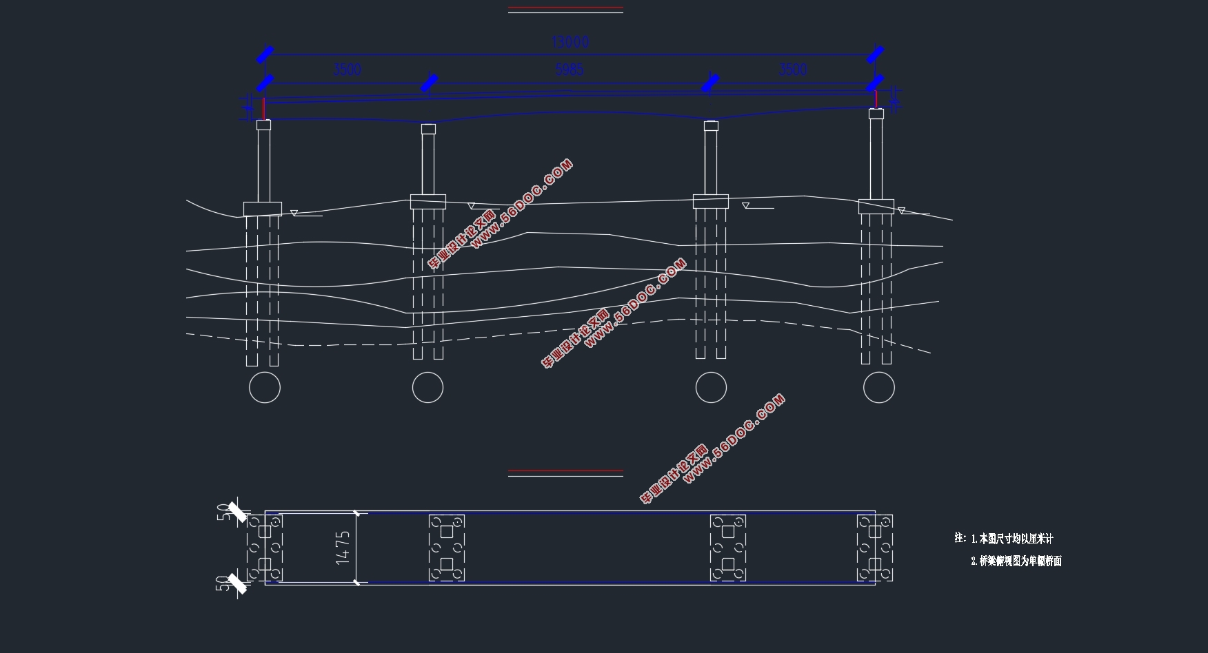
蚌埠五河跨淮北大堤及香浮规划堤引桥预应力混凝土连续梁桥桥长130m。按照设计任务书中的要求,本联设计要求采用变截面连续箱梁结构形式,布置时,通过计算调整,最终确定本联的跨径布置如下:
35m+60m+35 m =130m
由上图可知本联为三跨连续梁,由参考文献[1]第二章第一节(P69)可知,三跨连续梁合理的跨径布置为:边跨与中跨之比为0.5~0.8,且对称布置。该桥中选择的边跨与中跨之比为0.583:1。
1.1.2 计算跨径
上面的跨径布置为标准跨径,计算跨径还要考虑到两边跨伸缩缝及支座尺寸的折减。为了减小伸缩缝的宽度,把固定支座放在2#墩上,让梁体向两边伸缩。由设计任务书可知本桥的设计年平均温差为±20℃,混凝土材料的温度膨胀系数为1.0×10⁻⁵/℃,则可计算得左右两边的伸缩缝宽度至少分别为:10cm,10cm;再考虑到支座尺寸的影响,计算跨径布置如下图1-2:
0.5m+34.5+60m+34.5m+0.5m
目 录
摘 要 1
第一章 方案设计 1
1.1 跨径布置 1
1.2 顺桥向设计 2
1.3横桥向设计 2
第二章 恒载计算 5
2.1 节段划分及截面几何要素计算 5
2.2 一期恒载计算 6
2.3 二期恒载计算 6
2.4 总恒载计算 8
第三章 活载计算 10
3.1 汽车荷载 10
3.2 最大、最小弯矩及其对应的剪力计算 11
第四章 温度与支座沉降内力计算 17
4.1 温度次内力计算 17
4.2 支座沉降内力计算 25
第五章 内力组合及内力包络图 27
5.1 基本组合 27
5.2 頻遇组合 28
5.3 准永久组合 29
5.4 包络图 30
第六章 预应力筋的计算与布置 34
6.1 原理与方法 34
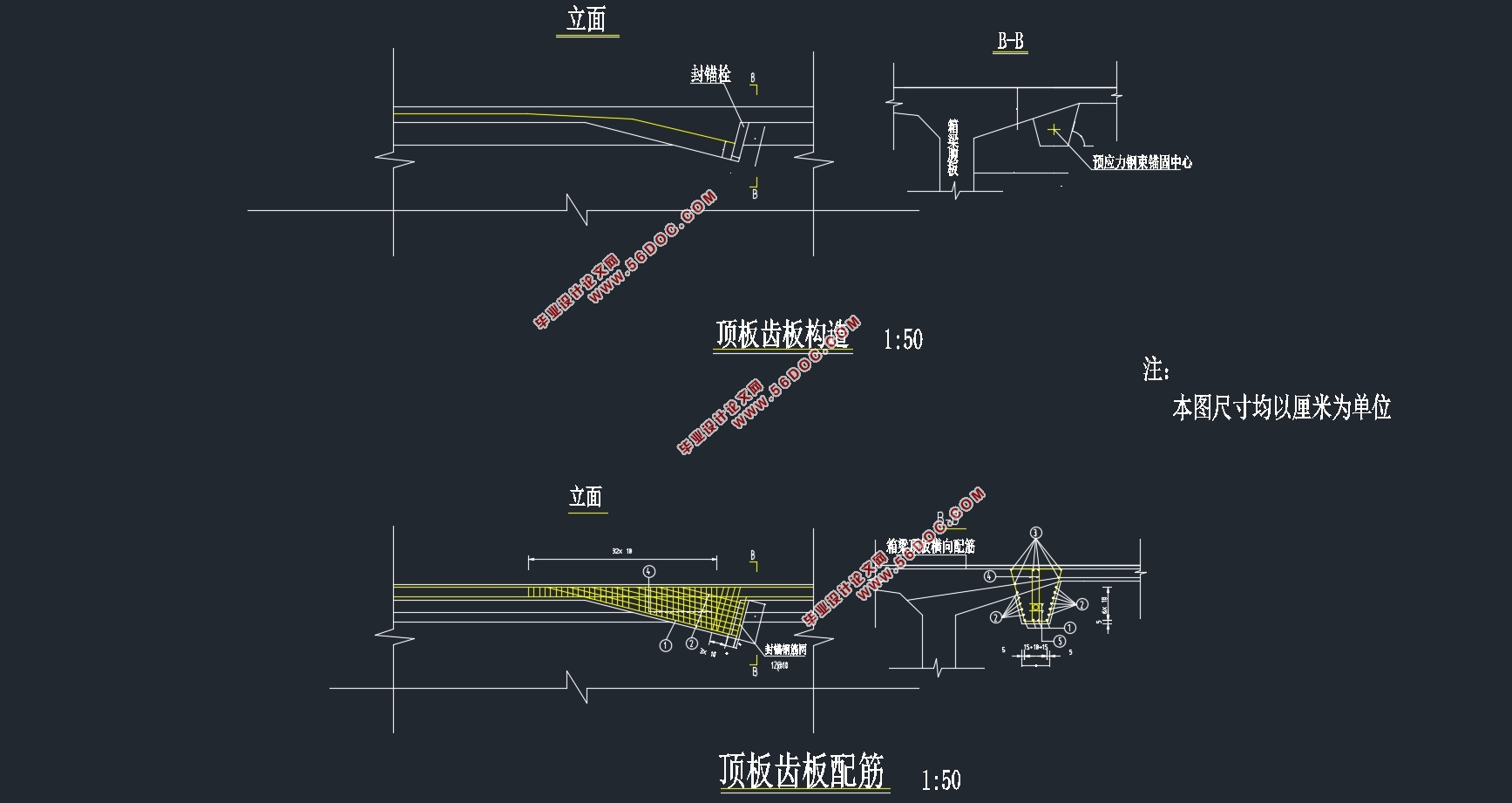
6.2 预应力筋的配置 34
6.3 钢束布置 37
第七章 净截面及换算截面几何特性计算 44
7.1 概述 44
7.2 净截面几何性质计算 44
7.3 换算截面性质计算 46
第八章 预应力损失及有效预应力计算 48
8.1 控制应力及有关参数计算 48
8.2 摩擦损失 48
8.3 锚具回缩损失 49
8.4 弹性压缩损失 50
8.5应力松弛损失 59
8.6收缩徐变损失 59
8.7预应力损失组合及有效预应力计算 60
第九章 承载能力极限状态验算 64
9.1 正截面承载力验算 64
9.2 斜截面抗剪承载力验算 67
第十章 正常使用极限状态验算 70
10.1 抗裂验算 70
第十一章 持久状况和短暂状况应力验算 73
11.1 持久状况截面混凝土法向应力验算 73
11.2 短暂状态应力验算 73
第十二章 墩及桩基础设计与计算 76
12.1 支座 76
12.2 墩身设计与验算 77
12.3 承台设计 79
12.4 桩基础设计 80
第十三章 工程造价用量 82
参考文献 84
致 谢 85
|