30m+55m+45m预应力钢筋混凝土梁桥施工图设计(含CAD图)(任务书,开题报告,论文计算书15000字,CAD图20张)
摘要
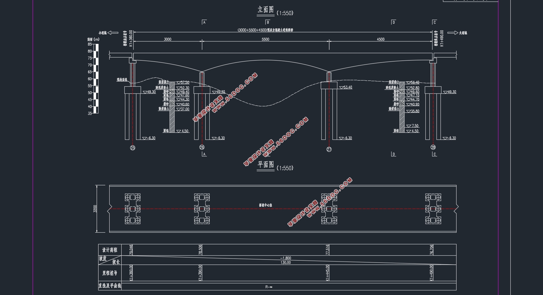
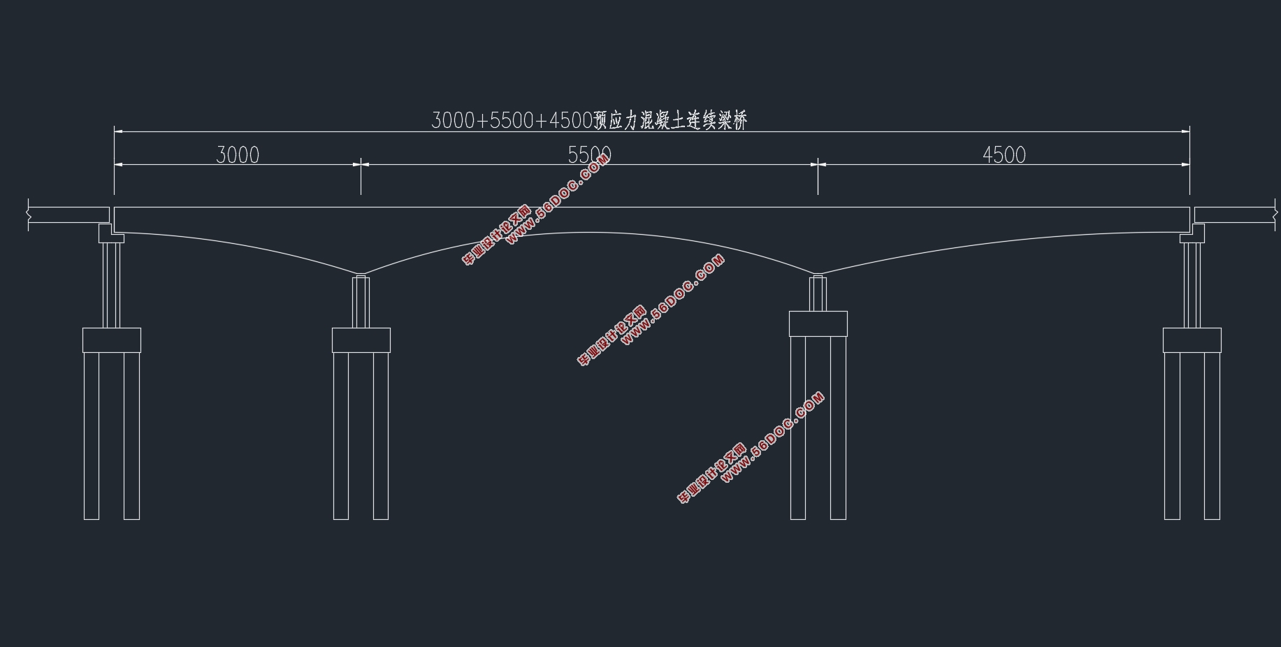
预应力混凝土梁桥作为交通建设中必不可少的重要组成部分, 在40-200 常常成为较理想的桥型。本次毕业设计就是选用预应力钢筋混凝土连续梁桥。本次设计的桥梁全长约130m,跨度为30m+55m+45m,桥梁宽度为32m,设计荷载为城市-A级。根据任务书要求,依据现行公路桥梁设计规范要完成对连续梁桥上、下结构设计计算并完成施工图设计。
本次设计采用MIDAS软件进行上部结构分析,依据实际的水文、地质条件,拟定上、下部和附属结构尺寸,定出桥梁设计方案。设计方案内容包括桥梁的平面布置图、纵断面图、横断面图。我们这次预应力钢筋混凝土梁桥的设计主要是上部结构的设计,
算、 主梁截面应力验算。同时在设计中也要考虑混凝土的收缩、徐变和温度次内力等影响。
最后,经过分析验算表明该设计计算方法的正确,内力分布合理,符合设计任务的要求。
关键词:预应力;连续梁桥;midas;上部结构
Abstract
As a necessary and important component of traffic construction, prestressed concrete beam bridge has developed rapidly. In the span of 40-200 meters, the prestressed concrete continuous girder bridge often becomes an ideal bridge type, whether from the angle of structure, force or economy.The graduation design is the use of prestressed concrete continuous beam bridge. The length of the bridge is about 130m, the span is 30m+55m+45m, the width of bridge is 32m, and the design load is city class A. According to the requirements of the task book, according to the current highway bridge design specifications, the design and calculation of the upper and lower structure of the continuous beam bridge should be completed and completed.
This design uses the MIDAS software to carry on the upper structure analysis, according to the actual hydrology, the geological condition, draws up the upper, the lower part and the subsidiary structure size, determines the bridge design plan.The design scheme includes the plane layout, vertical section and cross section of the bridge. We design the prestressed reinforced concrete beam bridge is the main design of the upper structure, it includes the overall layout and tendon position and size of the bridge, the various loads and combination of loads, reinforcement estimation, prestressing loss and at the same time in the design should also consider the influence of concrete shrinkage, creep and temperature force.
Finally, the analysis and calculation show that the design method is correct and the internal force distribution is reasonable, which meets the requirements of the design task.
Key words: prestressed; continuous beam bridge; Midas; superstructure
2.1.1技术标准
(1)公路等级:城市主干道
(2)设计速度:60km/h
(3)设计荷载:城市A级
(4)桥梁宽度:32m
(5)桥梁结构设计基准期:100年
(6)桥面横坡:双向2%
(7)环境类别:I类
(8)地震烈度: 0.05g, 0.35s。 为7 度

目录
第1章 绪论 1
1.1桥型方案的选择 1
1.2预应力混凝土连续梁桥的概述 2
1.3预应力混凝土连续梁桥施工方法介绍 3
第2章 设计依据及计算基本资料 4
2.1 主要技术标准和规范 4
2.1.1技术标准 4
2.1.2主要设计规范和标准 4
2.2主要材料 4
2.2.1混凝土材料 4
2.2.2钢筋 5
2.2.3预应力钢绞线 5
2.2.4其他材料 6
2.3地形地质的概况 6
2.3.1地形地貌 6
2.3.2地质条件 6
第3章 桥跨总体布置及结构主要尺寸 8
3.1桥型布置 8
3.2截面布置 8
3.2.1立面截面 8
3.2.2横截面 9
3.3梁高的尺寸 9
3.4箱梁构造与细部尺寸 9
3.4.1箱梁顶板 9
3.4.2箱梁底板 10
3.4.3箱梁腹板 10
3.4.4箱梁横隔板 10
3.4.5承托 10
3.5标准横截面图 11
第4章 行车道板计算 12
4.1基本信息 12
4.2中间桥面板计算 12
4.3悬臂板计算 15
4.4桥面板配筋 17
第5章 荷载内力计算 18
5.1建立计算模型 19
5.1.1单元的划分 19
5.1.2施工阶段的划分 19
5.2主梁恒载内力的计算 20
5.2.1主梁计算说明 20
5.2.2荷载内力计算 20
5.2.2.1自重荷载 20
5.2.2.2二期恒载 23
5.3活载内力的计算 25
5.3.1 汽车荷载 25
5.3.1.1汽车荷载 26
5.4次内力计算 29
5.4.1温度引起的内力计算 29
5.4.2支座位移引起的内力计算 31
5.5荷载组合 33
5.5.1 组合方法 33
5.5.2 承载能力极限状态的内力组合 33
5.5.3 正常使用极限状态 的内力组合 34
5.5.4 内力组合 35
第6 章 预应力钢束的估算与布置 37
6.1 预应力钢束的估算 38
6.1.1 计算原理 38
6.1.2按承载能力极限状态的强度要求计算 38
6.1.3按正常使用极限状态的应力要求计算 38
6.1.4预应力钢束面积估算结果 42
6.2预应力钢束的布置 43
6.2.1布置的原则 43
第7章 预应力损失及有效应力的计算 45
7.1预应力损失及有效应力的总体说明 45
7.2 预应力筋与管道壁间摩擦引起的应力损失 45
7.3锚具变形、钢筋回缩和接缝压缩引起的预应力损失 46
7.4混凝土弹性压缩引起的应力损失 46
7.5 钢筋松弛引起的应力损失 47
7.6混凝土收缩和徐变引起的应力损失 47
7.7钢筋的有效应力计算 48
第8章 主梁截面验算 50
8.1控制截面的选择 50
8.2截面强度验算 50
8.2.1正截面强度验算 50
8.2.2斜截面强度验算 52
8.3截面应力验算 53
8.3.1短暂状态的正应力验算 53
8.3.2持久状态的正应力验算 54
8.3.3主梁变形验算 55
第9章 下部结构计算 56
9.1尺寸布置及荷载信息 57
9.1.1尺寸布置 57
9.1.2 荷载信息 57
9.2桩长计算 58
9.3桩的内力及位移计算 60
9.3.1基本假定 60
9.3.2桩的内力计算(m法) 60
9.4桩基配筋计算及桩身材料截面强度验算 62
9.4.1桩身最大弯矩及其位置 62
9.4.2桩身截面强度验算 63
总结 65
参考文献 66
致谢 67
|