4×30mдЄгІСІЛьФ§ЭСЯШМђжЇКѓНсЙЙСЌајЯфСКЧХЪЉЙЄЭМЩшМЦ(КЌCADЭМ)(ТлЮФЫЕУїЪщ21000зж,CADЭМ11еХ)
еЊ вЊ
БОБЯвЕЩшМЦЬтФПЮЊ4×30mдЄгІСІЛьФ§ЭСЯШМђжЇКѓНсЙЙСЌајЯфСКЧХЪЉЙЄЭМЩшМЦЃЌЪЧвдЯхбєЪаЬЦКгДѓЧХжаЪЕМЪЯюФПЮЊБГОАЃЌЪєгкИУЯюФПв§ЧХЕФЕквЛСЊЕФЩЯВПНсЙЙКЭЯТВПНсЙЙМЦЫуЪщЁЃдЄгІСІЛьФ§ЭССЌајаЁЯфСКОпгаЪЉЙЄМђЕЅ,ааГЕЦНЫГЪц,ПЙе№ФмСІЧП,взгкБЃбјКЭЮЌЛЄЕФЬиЕуЁЃЪЪгУгкжааЁПчОЖЕФЧХСКЁЃЪмЪБМфМАИіШЫФмСІЕФЯожЦЃЌБОДЮБЯвЕЩшМЦЮДНјааКсЯђдЄгІСІЁЂЪњЯђдЄгІСІвдМАПЙе№ЕФЩшМЦЁЃ
БОДЮЩшМЦЪзЯШИљОнЙцЗЖвЊЧѓКЭЩшМЦОбщФтЖЈСЫжїСКЕФжївЊЙЙдьКЭЯрЙиЯИВПЕФГпДчЃЌПМТЧЕНЧХСКНсЙЙаЮЪНгыЕижЪЬѕМўЃЌЧХЬЈВЩгУРпАхЬЈЃЌЧХЖебЁгУдВжљЖеЃЌЛљДЁОљбЁгУФІВСзЎЁЃВЂШЗЖЈЪЉЙЄЗНЪНЮЊдЄжЦЕѕзАЪЉЙЄЁЃ
ЦфДЮРћгУMIDAS ШэМўНјааЩЯВПНсЙЙМЦЫуЗжЮіЃЌАќРЈФкСІЗжЮіЃЌМЦЫуХфНюНсЙћЃЌНјааЪЉЙЄНзЖЮМАНиУцбщЫуЁЃЭЌЪББиаыПМТЧЛьФ§ЭСЪеЫѕЁЂаьБфДЮФкСІКЭЕиЛљВЛОљдШГСНЕв§Ц№ЕФДЮФкСІвдМАЮТЖШДЮФкСІЕШвђЫиЕФгАЯьЁЃааГЕЕРАхЁЂУЊЯТОжВПгІСІгыЯТВПНсЙЙВЩгУЪжЫуЕФЗНЪНЃЌЯТВПНсЙЙжївЊНјааЧХЖеЁЂЧХЬЈвдМАзЎЛљДЁЕФЩшМЦгыМЦЫуЁЃ
ОЙ§ЗжЮіМЦЫуБэУїЃЌБОДЮЩшМЦЧХСКФкСІЗжВМКЯРэЃЌВЂЗћКЯЯргІЙцЗЖвЊЧѓЁЃ
ЙиМќДЪЃКЯШМђжЇКѓНсЙЙСЌајЃЛНсЙЙЗжЮіЃЛMIDAS/CIVIL
Abstract
The design of the construction of the continuous box girder bridge with 4 × 30m prestressed concrete is the background of the actual project of the Tanghe River Bridge in Xiangyang City. It belongs to the superstructure and the lower part of the first joint of the project Structure calculation book. Prestressed concrete continuous small box girder has the characteristics of simple construction, smooth driving, strong earthquake resistance, easy maintenance and maintenance. Suitable for small and medium span bridges. Due to the limitation of time and individual ability, this graduation design has not been designed for lateral prestress, vertical prestress and earthquake resistance.
In this design, the main structure and the relevant detail of the main girder are designed according to the requirements and design experience. Taking into account the bridge structure form and geological conditions, the abutment adopts the pylon table and the pier piers, and the foundation adopts the friction pile. And to determine the construction method for prefabricated lifting construction.
Second, the use of MIDAS software for the calculation of the upper structure analysis, including internal force analysis, calculation of reinforcement results, the construction phase and cross-section check. At the same time, it is necessary to consider the influence of the factors such as the shrinkage of the concrete, the internal force of the creep and the sub-internal force caused by the uneven settlement of the foundation and the internal force of the temperature. The design and calculation of the piers, abutment and pile foundation are mainly carried out by the lower part of the roadway, the local stress and the lower structure of the roadway.
After analysis and calculation shows that the design of the bridge internal force distribution is reasonable, and meet the corresponding regulatory requirements.
Key words: simple post - simple structure; structural analysis; MIDAS / CIVIL
Key words: rigid frame-continuous combination beam bridge; cantilever construction method;
MIDAS/CIVIL; structural analysis
ЩшМЦЗНАИ
ФтЖЈЕФШ§ИіЧХаЭЗНАИЃК
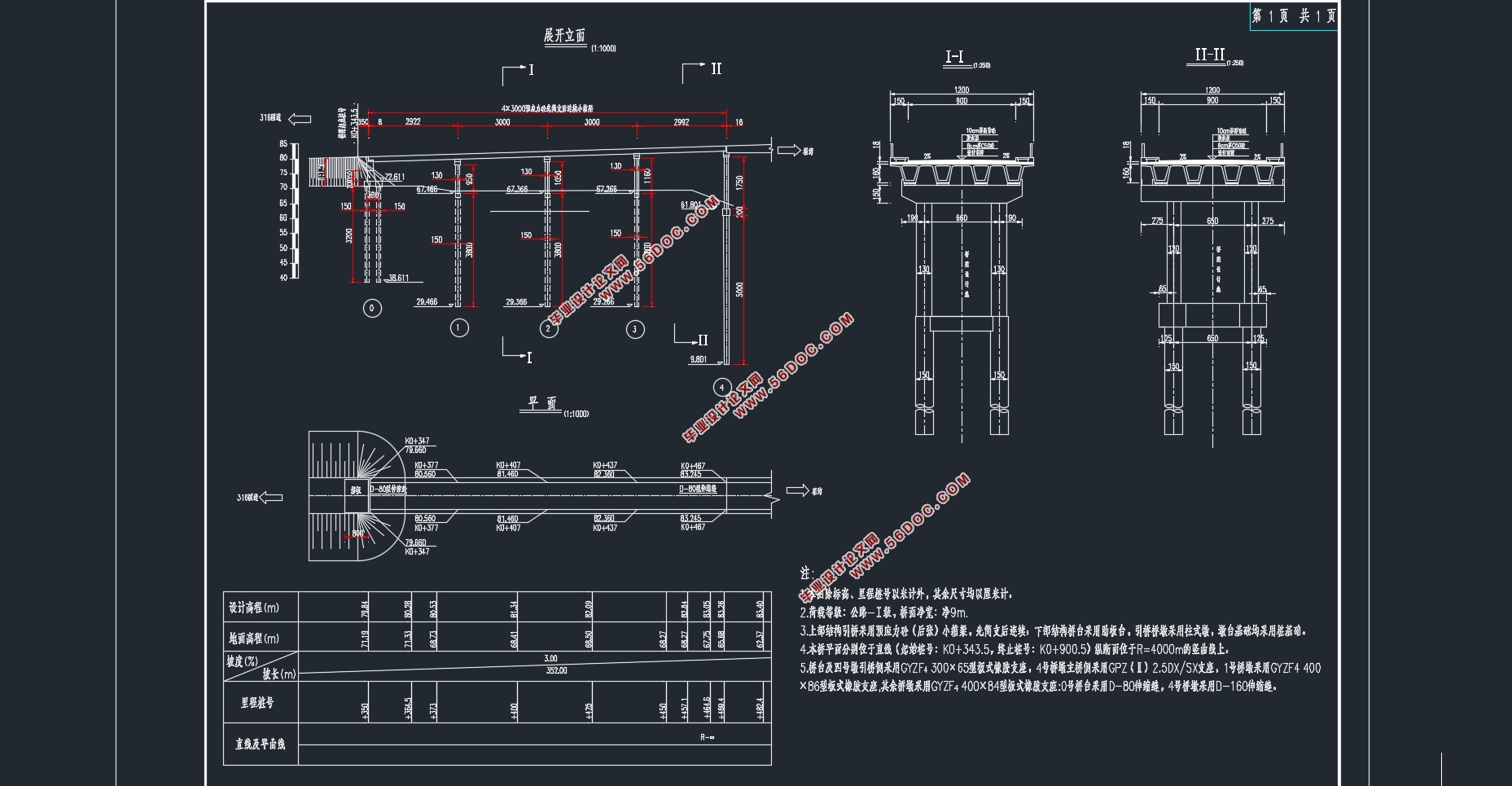
ЗНАИвЛЃК4×30mдЄгІСІЛьФ§ЭСЯШМђжЇКѓНсЙЙСЌајаЁЯфСКЧХЃЌШЋГЄ120mЃЛ
ЗНАИЖўЃК4×30mдЄгІСІЛьФ§ЭСЯШМђжЇКѓНсЙЙСЌајTСКЧХЃЌШЋГЄ120mЃЛ
ЗНАИШ§ЃК35+50+35дЄгІСІЛьФ§ЭСБфИпЖШСЌајЯфСКЧХЃЌШЋГЄ120mЁЃ
2.3.1 дЄгІСІЛьФ§ЭСЯШМђжЇКѓНсЙЙСЌајаЁЯфСКЧХ
1ЃЉПзОЖВМжУ4×30mЃЌШЋГЄ120mЃЌПэ12mЁЃЧХУцЩшга2%ЕФКсЦТЃЌЦфЭтВрБъИпЕЭгкжаМфБъИпЁЃ
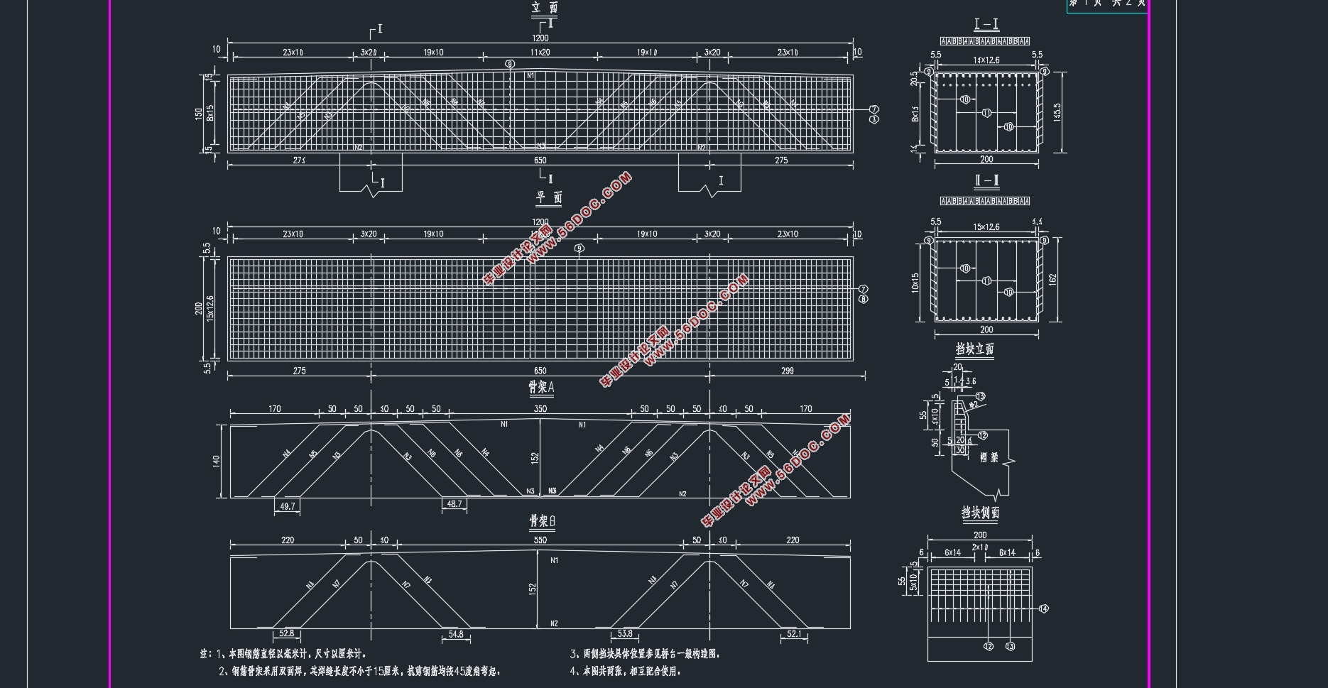
2ЃЉжїСКНсЙЙЃКШЋЧХУцВЩгУЕШНиУцЯфСКЃЌЖЅАхКёЖШ180cmЁЂЕзАхКёЖШ25cmЁЂвэдЕИљВП45cmЁЂвэдЕЖЫВПКёЖШ22cmЃЌБпСКПэЖШ2.85mЃЌжаСКПэЖШ2.4mЃЌСНЯфСКжЎМфЩш0.5mЪЊНгЗьЪЙНсЙЙСЌНгГЩећЬхЁЃУППчЩшга4ЦЌЯфСКЃЌШЋЧХЙВ16ЦЌЯфСКЁЃ
3ЃЉВЩгУЫЋдВжљЪНЧХЖеЃЛзЎЛљДЁЃЈзЊПзЙрзЂзЎЃЉЁЃ
4ЃЉЪЉЙЄЗНАИЃКВЩгУзАХфЪНЪЉЙЄЗНЗЈЃЌЯШМђжЇКѓНсЙЙСЌајЁЃ
5ЃЉзАХфЪНСЌајЯфСКЧХЕФЗЂеЙЃК
2.3.2 зАХфЪНдЄгІСІЛьФ§ЭСМђжЇTСК
3ЃЉЯТВПНсЙЙЃКВЩгУЫЋдВжљЪНЧХЖеЃЛзЎЛљДЁЃЈзъПзЙрзЂзЎЃЉЁЃ
4ЃЉЪЉЙЄЗНАИ:ВЩгУзАХфЪНЪЉЙЄЗЈЁЃ
5ЃЉзАХфЪНдЄгІСІЛьФ§ЭСМђжЇT СКЕФЗЂеЙЃК
2.3.3 дЄгІСІЛьФ§ЭСБфИпЖШСЌајЯфСКЧХ
1ЃЉПзОЖВМжУЃК35m+50m+35m,ШЋГЄ120mЃЌПэ12mЁЃЧХУцЩшга1.5 ЃЅЕФКсЦТЃЌЦфжаМфБъИпИпгкЭтВрБъИпЁЃ
2ЃЉжїСКНсЙЙЃКЩЯВПНсЙЙЮЊдЄгІСІБфИпЖШСЌајЯфСКЁЃВЩгУЕЅЯфЕЅЪваЮЪНЃЌжЇЕуДІЯфСКИп4mЃЌПчжаДІЯфСКИп2mЁЃжївЊВЩгУИпЧПЛьФ§ЭСвдМАДѓЖжЮЛдЄгІСІЬхЯЕРДЪЕЯжжїСКЕФЧсаЭЛЏЁЃ
3ЃЉЯТВПНсЙЙЃКВЩгУЫЋдВжљЧХЖеЃЛзЎЛљДЁЃЈзъПзЙрзЂзЎЃЉЁЃ
4ЃЉЪЉЙЄЗНАИЃКШЋЧХВЩгУдЄжЦЕѕзАЪЉЙЄЁЃ
5ЃЉдЄгІСІЛьФ§ЭСБфНиУцСЌајСКЧХЗЂеЙИХПіЃК

ФП ТМ
еЊ вЊ I
Abstract II
Ек1еТ аїТл 5
1.1 дЄгІСІЛьФ§ЭССЌајСКЧХЕФЗЂеЙИХЪі 5
1.2 бЁЬтЩшМЦЫМЯыМАвтвх 5
Ек2еТ ЧХаЭЗНАИБШбЁ 6
2.1 ЙЙЫМзкжМ 6
2.2 БШбЁддђ 6
2.3 ЩшМЦЗНАИ 6
2.3.1 дЄгІСІЛьФ§ЭСЯШМђжЇКѓНсЙЙСЌајаЁЯфСКЧХ 6
2.3.2 зАХфЪНдЄгІСІЛьФ§ЭСМђжЇTСК 7
2.3.3 дЄгІСІЛьФ§ЭСБфИпЖШСЌајЯфСКЧХ 7
Ек3еТ ЧХПчзмЬхВМжУМАНсЙЙГпДчФтЖЈ 9
3.1 ЧХПчВМжУ 9
3.2 ЩЯВПНсЙЙГпДчФтЖЈ 9
3.2.1 ЫГЧХЯђжїСКГпДчФтЖЈ 10
3.2.2 КсЧХЯђжїСКГпДч 10
3.3 ЯТВПНсЙЙГпДчЕФФтЖЈ 10
3.3.1 ЖеЩэГпДчФтЖЈ 10
3.3.2 ЧХЬЈФтЖЈ 10
3.3.3 зЎЛљДЁГпДчФтЖЈ 11
Ек4еТ НЈФЃ 11
4.1 ФЃаЭМђЛЏ 12
4.1.1 КсЯђЗжВМЯЕЪ§ЕФМЦЫу 12
4.1.2 ФЃаЭМђЛЏ 12
4.2 жївЊВЮЪ§ЫЕУї 13
4.2.1 ВФСЯВЮЪ§ 13
4.2.2 КЩдиВЮЪ§ 14
4.2.3 БпНчЫЕУї 15
4.3 ЪЉЙЄНзЖЮЫЕУї 15
Ек5еТ ЧХСКНсЙЙФкСІМЦЫу 15
5.1 КудиФкСІ 16
5.2 ЛюдиФкСІ 20
Ек6еТ дЄгІСІИжНюЩшМЦМАдЄгІСІЫ№ЪЇМЦЫу 24
6.1 дЄгІСІИжНюЩшМЦ 24
6.1.1 знЯђдЄгІСІНюЙРЫу 24
6.1.2 дЄгІСІНюЕФВМжУ 28
6.2 дЄгІСІЫ№ЪЇ 28
6.2.1 дЄгІСІИжНюгыЙмЕРБкжЎМфЕФФІВС 28
6.2.2 УЊОпБфаЮЁЂИжНюЛиЫѕКЭНгЗьбЙЫѕ 29
6.2.3 дЄгІСІИжНюгыЬЈзљжЎМфЕФЮТВю 29
6.2.4 ЛьФ§ЭСЕФЕЏадбЙЫѕ 29
6.2.5 дЄгІСІИжНюЕФгІСІЫЩГк 30
6.2.6 ЛьФ§ЭСЕФЪеЫѕаьБф 30
6.2.7 дЄгІСІЫ№ЪЇМЦЫуНсЙћ 31
Ек7еТ ДЮФкСІМЦЫуМАФкСІзщКЯ 33
7.1 ЮТЖШДЮФкСІ 33
7.1.1 МЦЫувРОнМАЗНЗЈ 33
7.1.2 ЮТЖШДЮФкСІМЦЫуНсЙћ 34
7.2 ЛљДЁВЛОљдШГСНЕДЮФкСІ 39
7.3 дЄгІСІДЮФкСІ 41
7.4 ЪеЫѕДЮФкСІ 43
7.5 аьБфДЮФкСІ 46
7.6 ФкСІзщКЯ 48
7.6.1 ГадиФмСІМЋЯозДЬЌзщКЯ 48
7.6.2 е§ГЃЪЙгУМЋЯозДЬЌзщКЯ 50
Ек8еТ жївЊНиУцбщЫу 53
8.1 ГадиФмСІМЋЯозДЬЌНиУцбщЫу 54
8.1.1 е§НиУцПЙЭфбщЫу 54
8.1.2 аБНиУцПЙМєбщЫу 56
8.2 е§ГЃЪЙгУМЋЯозДЬЌНиУцбщЫу 57
8.2.1 ЪЙгУНзЖЮе§НиУцПЙСббщЫу 58
8.2.2 ЪЙгУНзЖЮаБНиУцПЙСббщЫу 60
8.2.3 ФгЖШбщЫу 61
8.3 ГжОУзДПіКЭЖЬднзДПіЙЙМўЕФгІСІбщЫу 62
8.3.1 ЪЙгУНзЖЮе§НиУцбЙгІСІбщЫу 62
8.3.2 ЪЙгУНзЖЮаБНиУцжїбЙгІСІбщЫу 63
8.3.3 ЪЉЙЄНзЖЮе§НиУцЗЈЯђгІСІбщЫу 64
8.3.4 ЪмРЧјИжНюЕФРгІСІбщЫу 67
Ек9еТ УЊЯТОжВПГабЙбщЫу 68
9.1 ОжВПЪмбЙЧјГпДчвЊЧѓ 69
9.2 ОжВППЙбЙГадиСІМЦЫу 70
Ек10еТ ааГЕЕРАхМЦЫу 70
10.1 жаМфЕЅЯђАхМЦЫу 71
10.1.1 КудиФкСІ 71
10.1.2 ЛюдиФкСІ 71
10.1.3 ФкСІзщКЯ 73
10.2 ЭтБпСКаќБлАхФкСІМЦЫу 74
10.2.1 КудиФкСІ 74
10.2.2 ЛюдиФкСІ 74
10.2.3 ФкСІзщКЯ 75
10.3 ХфНюЩшМЦ 75
10.3.1 жЇЕуДІХфНю 76
10.3.2 ПчжаХфНю 76
Ек11еТ ЧХЖеМЦЫу 77
11.1 КЩдиМЦЫу 77
11.2 НиУцХфНюМЦЫу 78
11.3 ЖежљНиУцГадиСІбщЫу 80
Ек12еТ ЧХЖезъПзЙрзЂзЎМЦЫу 80
12.1 КЩдиМЦЫу 81
12.2 зЎГЄМЦЫу 81
12.3 зЎЕФФкСІМАЮЛвЦМЦЫу 83
12.3.1 ЛљБОМйЖЈ 83
12.3.2 зЎЕФМЦЫуПэЖШ 83
12.3.3 зЎЕФБфаЮЯЕЪ§ 83
12.3.4 МЦЫузюДѓГхЫЂЯпДІзЎЩэЭфОи ЃЌЫЎЦНСІ МАжсЯђСІ 84
12.3.5 зЎЩэзюДѓЭфОиЮЛжУМАЭфОиМЦЫу 84
12.3.6 МЦЫузюДѓГхЫЂЯпвдЯТЩюЖШ ДІзЎНиУцЩЯЕФЭфОи МАЫЎЦНбЙгІСІ 84
12.3.7 зЎЖЅзнЯђЫЎЦНЮЛвЦбщЫу 87
12.4 зЎЩэНиУцХфНюМЦЫу 88
12.5 ЖежљНиУцГадиСІбщЫу 89
Ек13еТ ЧХЬЈМЦЫу 90
13.1 ИЧСКМЦЫу 91
13.1.1 МЦЫуФЃаЭ 91
13.1.2 ИЧСКНиУцХфНю 92
13.1.3 ИЧСКНиУцГадиСІбщЫу 93
13.2 зъПзЙрзЂзЎ 96
Ек14еТ МђжЇзЊСЌајЖЫВПННжўЫГађЕФЬНЬж 96
14.1 МИжжПЩФмЕФЪЉЙЄЫГађгыЦРХаБъзМ 96
14.2 МЦЫуНсЙћгыЗжЮі 97
14.2.1 ПчжаФгЖШЕФЗжЮі 97
14.2.2 ПчжаЭфОиЕФЗжЮі 97
14.2.3 ПчжаФкСІЗжЮі 97
14.2.4 СЌајЖЫФкСІЗжЮі 98
14.2.5 СЌајЖЫЭфОиЗжЮі 98
14.3 НсТл 99
ВЮПМЮФЯз 99
жТ аЛ 101
|