公路(56+100+100+56)m预应力混凝土连续刚构桥设计(含CAD图)(任务书,开题报告,论文说明书21000字,CAD图13张)
摘 要
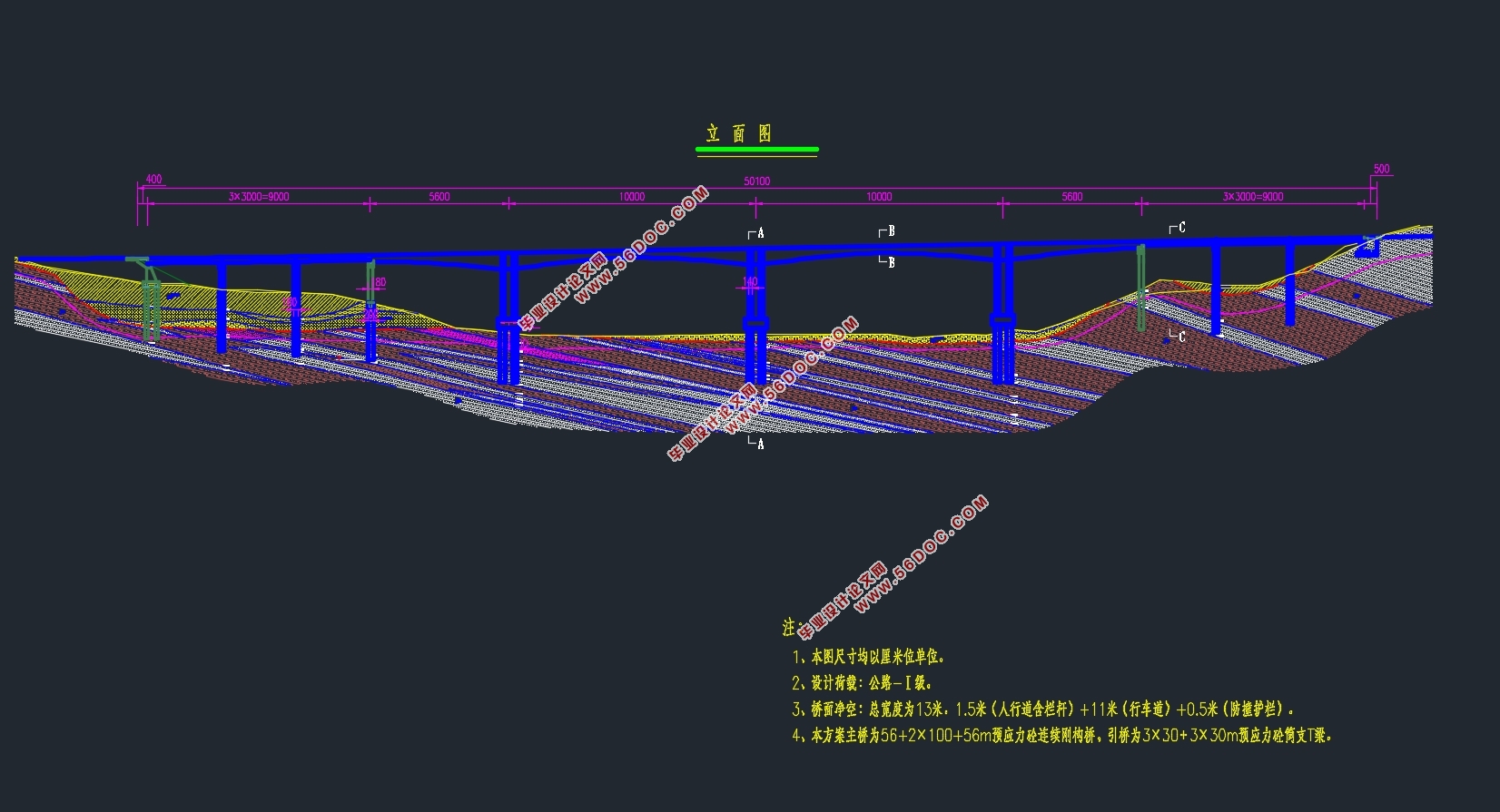
本次毕业设计是对连续刚构桥进行初步设计。此桥型不但具有T型刚构桥不设或少设支座、施工无需转换体系的特点,而且还包括了连续梁桥少量伸缩缝、行车平顺的优点。以河市洲河大桥为背景,对其进行初步设计。桥梁跨径为56+100+100+56m,采用单箱单室截面,桥面宽13m,公路等级:一级公路,设计行车速度: ,车道荷载:公路—Ⅰ级。
主要设计流程如下:
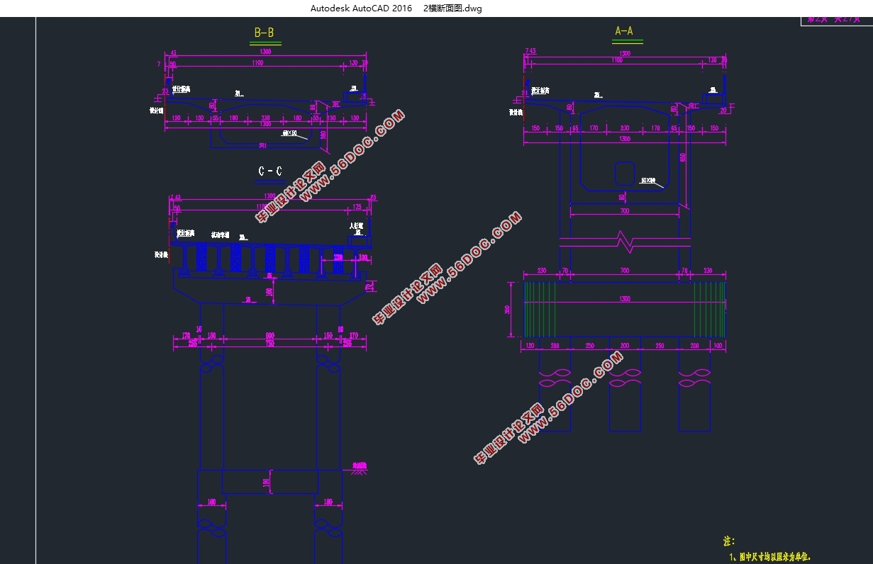
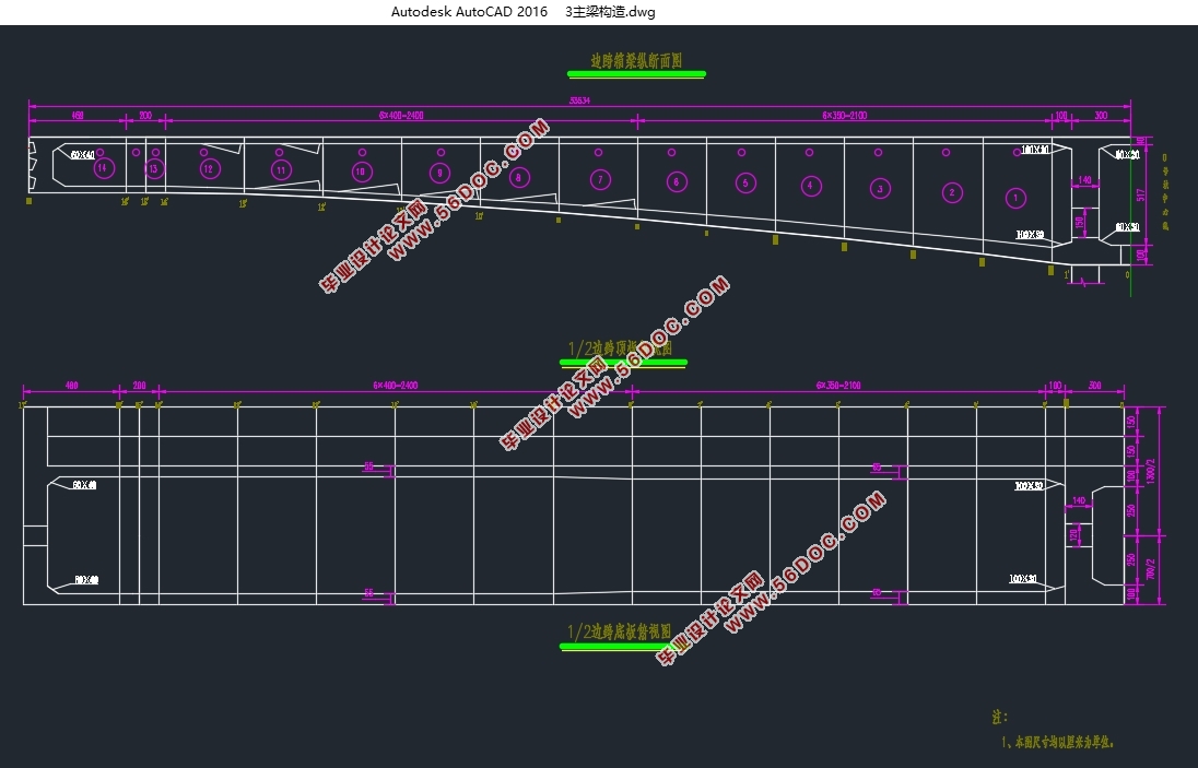
首先是对主梁构造尺寸的拟定。变截面的主梁,使得梁底曲线呈现抛物线的形式。此方法不仅仅能够有效减轻自重,而且使桥梁线性更加优美。其次,根据悬臂施工挂篮的起吊能力,对主梁进行施工阶段的划分。本次设计将主梁划分为15个施工阶段。接着根据地质情况设计桥梁下部结构。
最后,根据已经设计的构造尺寸,在Midas /Civil软件中建立模型,进行桥梁结构内力分析,预应力钢筋的束和调束,预应力损失的计算,次内力的,以及截面验算。同时对于桥梁下部结构进行了相关手算。其中主要截面验算中均满足抗弯、抗压、以及抗裂验算要求;下部结构的承载力也符合规范所要求的安全系数;荷载组合作用下,桥梁变形也满足规范要求。
关键词:Midas /Civil;连续刚构桥;悬臂施工;结构计算
Abstract
This graduation design is a preliminary design for the continuous rigid frame bridge. The bridge not only have T rigid frame bridge is not buy less support, without conversion system construction, but also includes the advantages of continuous girder bridge a small amount of expansion joint, driving a smooth. Based on the river bank bridge, a preliminary design was carried out. Bridge spans of 56 + 100 + 100 + 56 m, with single box section, wide and 13 m bridge and road level: the first class road, driving speed: design, lane load: highway —Ⅰ level.
The main design process is as follows:
The first is the design of the structural dimensions of the main girders. The main beam of the cross section makes the bottom curve of the beam appear a parabola. This method is not only effective in reducing the weight, but also makes the bridge more beautiful. Secondly, according to the lifting ability of the hanging basket, the construction phase of the main beam is divided. This design divides the main beam into 15 construction stages. Then the structure of the bridge is designed according to geological conditions.
Finally, according to have design the structure size, build a model in the software Midas/Civil, internal force of bridge structure is analyzed, the prestressed beam and beams, the calculation of the loss of prestress, times of internal force, as well as the cross section calculation. At the same time, the relative hand calculation is carried out for the lower structure of the bridge. The main section of the test is the requirement of the anti-bending, anti-pressure and anti-cracking. The bearing capacity of the lower structure also meets the safety factor required by the specification; Under load combination, the bridge deformation meets the specification requirement.
Key Words:Midas/Civil;continuous rigid frame bridge;cantilever construction;structural calculation

目 录
第1章绪论 1
1.1连续刚构桥 1
1.2预应力混凝土连续刚构桥的施工方法 4
第2章基本资料、技术标准、设计依据及要求 5
2.1基本资料 5
2.2设计标准 6
2.3主要技术标准及采用规范 7
第3章桥梁总体布置及结构主要尺寸 8
3.1方案比选 8
3.2桥跨布置 9
3.3上部结构尺寸拟定 10
3.3.1横桥向主梁尺寸的拟定 10
3.3.2顺桥向主梁尺寸的拟定 12
3.4下部结构尺寸拟定 13
3.4.1墩身尺寸拟定 13
3.4.2桩基础尺寸拟定 14
3.4.3承台尺寸拟定 14
第4章建立模型 15
4.1概述 15
4.2模型节段的划分 15
4.3材料参数 16
4.4截面的定义以及边界条件的添加 17
4.5荷载参数 18
4.6施工阶段定义 18
4.7完成模型 20
第5章桥梁结构内力计算 21
5.1恒载内力 21
5.2活载内力 25
第6章预应力钢筋设计及预应力损失计算 29
6.1预应力钢筋布置 29
6.1.1预应力钢筋构造要求 29
6.1.2预应力束布置原则 29
6.2纵向预应力筋估算 29
6.3预应力损失及有效预应力计算 32
6.3.1概述 32
6.3.2预应力筋与管道之间的摩擦引起的预应力损失 33
6.3.3锚具变形、钢筋回缩和接缝压缩引起的应力损失 33
6.3.4预应力钢筋与台座之间的温差引起的损失 34
6.3.5混凝土弹性压缩损失 34
6.3.6预应力钢筋松驰引起的应力损失 34
6.3.7混凝土收缩和徐变引起的预应力损失 35
6.3.8预应力损失计算结果 36
第7章次内力计算及内力组合 41
7.1温度次内力 41
7.1.1温度变化次内力的计算方法 41
7.1.2温度次内力计算结果 42
7.2预应力次内力 46
7.2.1预应力次内力计算方法 46
7.2.2预应力次内力计算结果 46
7.3 收缩次内力 49
7.4徐变次内力 53
7.5内力组合 56
7.5.1承载能力极限状态设计 56
7.5.2正常使用极限状态设计 59
第8章主要截面验算 62
8.1使用阶段正截面抗弯验算 62
8.2施工阶段法向压应力验算 64
8.3使用阶段正截面压应力验算 67
8.4使用阶段斜截面抗裂验算 69
第9章 下部结构计算 71
9.1桥墩计算 71
9.1.1 内力计算 71
9.1.2 截面设计 71
9.1.3 截面复核 72
9.2钻孔灌注桩计算 73
9.2.1 基本假定 73
9.2.2 桩径桩长拟定 73
9.2.3 桩基础内力计算 73
9.2.4 桩基础内力验算 79
9.2.5 桩身配筋计算 80
参考文献 82
致谢 83
|