侧弯支架冷冲压工艺及级进模设计(任务书,开题报告,外文翻译,进度计划表,论文说明书30000字,CAXA图纸5张)
摘 要
金属板料冲压是一种在工业生产中应用广泛的加工方法。随着现代各行各业突飞猛进的发展,金属件的结构复杂,精度高,需求量多,加上对生产的安全性、操作的方便性,加工的经济性等要求也日益提高,采用单工位模具已经无法满足生产的需要,许多制造商均采用多工位级进模进行生产。因此,多工位级进模在国内外模具制造业中应用日趋广泛。多工位级进模是在普通级进模的基础上发展起来的一种模具,是当代所有模具中冲压功能最多、结构最复杂、生产效率和自动化程度最高的一种冲模。在多工位级进模结构设计过程中,首先必须设计级进模的总装结构,然后再在此基础上进行模具其他零部件的设计。本模具采用切废料方式进行冲裁,故模具结构采用冲孔、导正、弯曲、落料的工序设计,排样采用单排横排排列。本论文分析了侧弯支架的冲压工艺性,介绍了侧弯支架多工位级进模总体结构设计,对工件进行了展开计算,确定了工件加工成型的工艺方案和排样方案,对模具进行了工艺计算,根据计算结果进行了凸模、凹模、垫板、导料板、卸料板、镶块等主要零部件的设计,还根据各标准对模具中用到的其他标准件,如模架、导柱导套等,进行了选择与设计。实践证明:该模具结构合理、可靠,并能保证产品质量,对此类零件的级进模设计有参考价值。
关键词:侧弯支架;冲压工艺;排样;连续模
Abstract
Sheet metal stamping is a widely used method in industrial production.With the rapid development of modern businesses,the structure of the metal pieces becomes more and more complex. The metal pieces also need to have high accuracy. At the same time, the demands of the production security, the ease of operation, the economy of processing are increasing. Single-stage molds can’t meet the the needs of production. Many manufacturers use the multi-position progressive die in production. Therefore, Multi-position Progressive Dies are used increasingly widespread in the die manufacturing at home and abroad.Multi-position Progressive Die is developed basing on the general progressive die. It has the most pressing function, the most complex structure, productivity and the highest degree of automation. In the design of the multi-position progressive die, we must design the assembly structure of the progressive die. And then, we design other components of it.This mold adopts the blanking, cutting waste way so the mould structure is punch, guide, bending, blanking process design, layout using single side-by-side arrangement. In this page, I analyzed the stamping process of a scoliosis bracket, as well as design of the verall structure. I also did the calculation of the workpiece, determined the workpiece’s forming process and the nesting program and did a calculation of the mold process. After that, I designed the die in all aspects. The application shows that the die is feasible and reliable in structure and can ensure the quality of the products.
Key words: Scoliosis bracket;Stamping process;Layout design;Progressive die
本课题应达到的要求
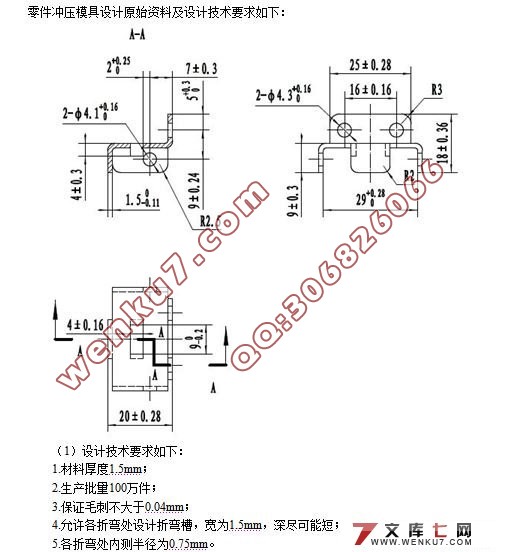
零件冲压模具设计原始资料及设计技术要求如下:
(1)设计技术要求如下:
1.材料厚度1.5mm;
2.生产批量100万件;
3.保证毛刺不大于0.04mm;
4.允许各折弯处设计折弯槽,宽为1.5mm,深尽可能短;
5.各折弯处内测半径为0.75mm。
(2)指导思想:
利用所学知识,根据冲压件复杂结构形状等信息,进行级进模结构的设计,并在CAXA等软件下绘制模具结构图,提高我们对专业知识的综合运用能力,准确地把握模具行业的发展方向。
2 冲压工艺设计
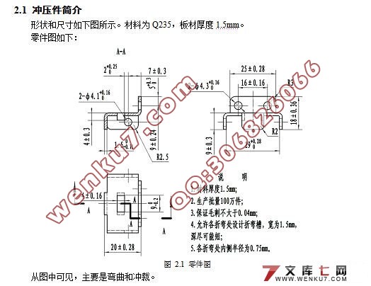
2.1 冲压件简介
形状和尺寸如下图所示。材料为Q235,板材厚度1.5mm。

目 录
摘 要 III
Abstract IV
目 录 V
1 绪 论 1
1.1 课题研究的目的和意义 1
1.2 国内外的发展概况 2
1.3 本课题应达到的要求 5
2 冲压工艺设计 6
2.1 冲压件简介 6
2.2 冲压的工艺性分析 6
2.3 冲压工艺方案的确定 8
2.3.1 冲压模具类型 8
2.3.2 冲压工艺分析和计算 8
3 侧弯支架连续模设计 10
3.1 模具结构 10
3.2 确定其搭边值 11
3.3 确定排样图 11
3.3.1 送料步距与带料宽度 11
3.3.2 排样方案 13
3.4 材料利用率计算 13
3.5 凸、凹模等刃口尺寸的确定 14
3.5.1 冲孔凸、凹模刃口尺寸计算 14
3.5.2 成形侧刃凸、凹模刃口尺寸计算 16
3.5.3 小凸形凸、凹模刃口尺寸计算 18
3.5.4 大凸形凸、凹模刃口尺寸计算 19
3.5.5 凹形凸、凹模刃口尺寸计算 20
3.5.6 长矩形凸、凹模刃口尺寸计算 21
3.5.7 短矩形凸、凹模刃口尺寸计算 22
3.5.8 切断凸、凹模刃口尺寸计算 23
3.5.9 前弯曲凸、凹模刃口尺寸计算 24
3.5.10 后弯曲凸、凹模刃口尺寸计算 25
3.5.11 左右弯曲凸、凹模刃口尺寸计算 25
3.5.12 中间切舌凸、凹模刃口尺寸计算 26
3.6 冲压力计算 26
3.6.1 冲孔部分冲压力 27
3.6.2 成形侧刃冲压力 28
3.6.3 切废料部分冲压力 28
3.6.4 弯曲部分冲压力 29
3.6.5 切舌弯曲部分冲压力 29
3.6.6 切断部分冲压力 30
3.6.7 总冲压力 30
3.7 压力机选用 31
3.8 压力中心计算 31
3.9 模具主要零部件的结构设计 32
3.9.1 凹模结构及设计 32
3.9.2 圆凸模1的结构设计 34
3.9.3 圆凸模2的结构设计 34
3.9.4 方形凸模的结构设计 35
3.9.5 成形侧刃的结构设计 36
3.9.6 小凸形凸模的结构设计 36
3.9.7 大凸形凸模的结构设计 37
3.9.8 凹形凸模的结构设计 38
3.9.9 长矩形凸模的结构设计 38
3.9.10 短矩形凸模的结构设计 39
3.9.11 前弯曲凹模镶块的结构设计 40
3.9.12 前弯曲凸模的结构设计 40
3.9.13 U型弯曲半凹模的结构设计 41
3.9.14 弯曲切断组合凸模的结构设计 42
3.9.15 切舌弯曲凸模的结构设计 42
3.9.16 切断弯曲凸凹模的结构设计 43
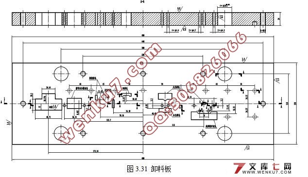
3.9.17 卸料板设计 44
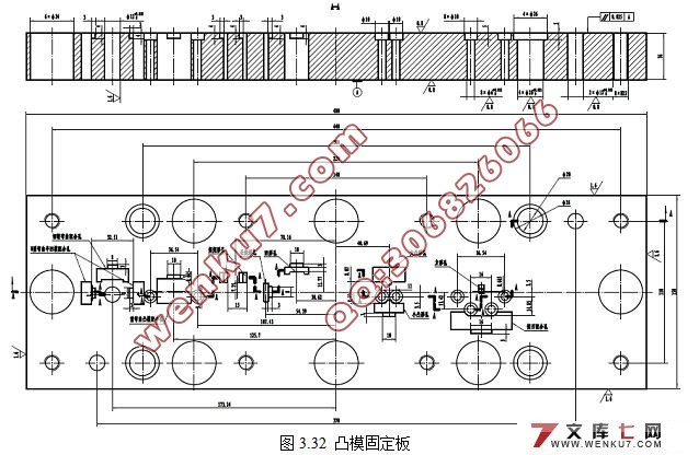
3.9.18 凸模固定板设计 44
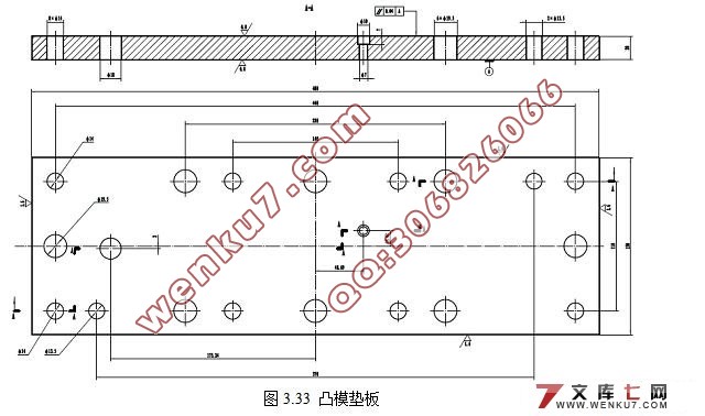
3.9.19 凸模垫板设计 45
3.9.20 凹模垫板设计 46
3.9.21 挡块设计 46
3.10 标准件确定 47
3.10.1 模架确定 47
3.10.2 上模螺钉确定 47
3.10.3 上模销确定 47
3.10.4 下模螺钉确定 47
3.10.5 下模销确定 47
3.10.6 卸料螺钉确定 48
3.10.7 卸料弹簧设计 48
3.10.8 U型弯曲顶件弹簧设计 48
3.10.9 U型弯曲推件弹簧设计 48
3.10.10 切舌弯曲顶件弹簧设计 48
3.10.11 U型弯曲凸模固定螺钉确定 49
3.10.12 大凸形凸模固定螺钉确定 49
3.10.13 挡块固定螺钉确定 49
3.10.14 小导柱确定 49
3.10.15 凹模上小导套2确定 49
3.10.16 卸料板上小导套1确定 49
3.10.17 抬料销确定 49
3.10.19 抬料销弹簧设计 50
3.10.20 挡块销确定 50
3.11 模具闭合高度、校验压力机 50
4 结论与展望 51
4.1 结论 51
4.2 不足之处及未来展望 51
致 谢 52
参考文献 53
|
