剃须刀后盖注塑模具设计(含CAD零件图和装配图)
来源:wenku7.com 资料编号:WK710897 资料等级:★★★★★ %E8%B5%84%E6%96%99%E7%BC%96%E5%8F%B7%EF%BC%9AWK710897
以下是资料介绍,如需要完整的请充值下载。
1.无需注册登录,支付后按照提示操作即可获取该资料.
2.资料以网页介绍的为准,下载后不会有水印.资料仅供学习参考之用. 密 保 惠 帮助
资料介绍
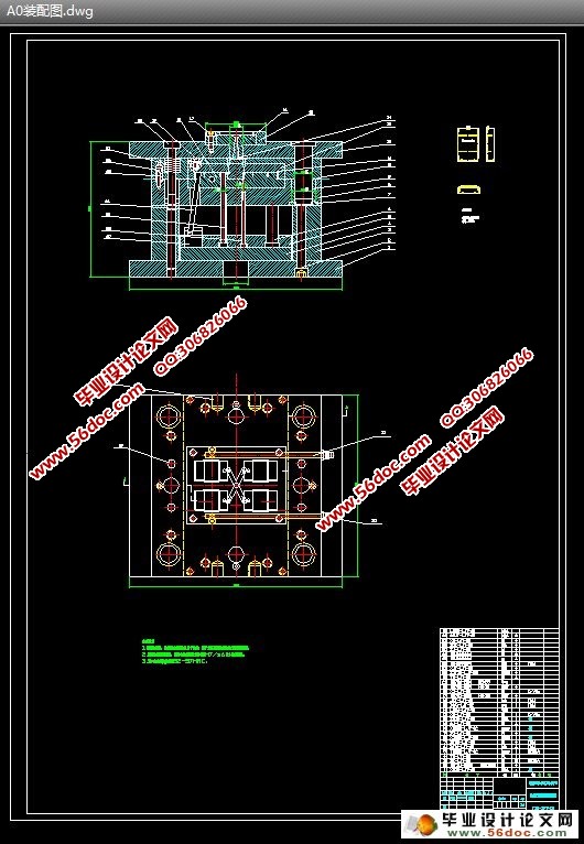
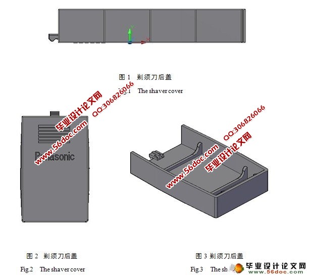
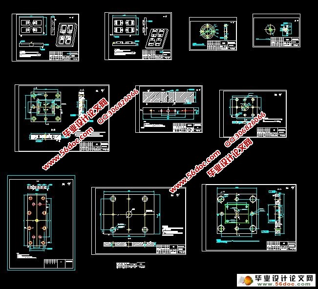
剃须刀后盖注塑模具设计(含CAD零件图和装配图)(选题审批表,任务书,开题报告,中期检查表,论文说明书17700字,CAD图11张)
摘 要:塑料工业是当今世界上增长最快的工业门类之一,而注塑模具是其中发展较快的种类,因此,研究注塑模具对了解塑料产品的生产过程和提高产品质量有很大意义。本模具设计的课题是剃须刀后盖,针对其进行了相关的工艺设计和模具设计。设计中利用CAD软件对模具进行计算分析,提高了模具设计合理性。介绍了注射成型的基本原理,特别是单分型面注射模具的结构与工作原理,对注塑产品提出了基本的设计原则;详细介绍了冷流道注射模具浇注系统和顶出系统的设计过程,并对模具强度要求做了说明;最后对导柱和导套进行了参数化设计。本模具在节约模具成本、缩短生产周期、提高模具寿命取得了较大的成就。
关键词:注塑模;剃须刀后盖;冷流道;浇注系统;顶出系统。
The Design of Shaver Cover Injection Mold
Abstract:Plastic industry is one of the quickest industry classes that develops in the world, and the injection mold is among the development, therefore, the research on the injection mold pays large significance on the understanding of the production process of the plastic product and improvement of the product quality. This mold design's topic is the shaver cover, according to the related shaver cover,I did associated process design and die design. In this design,I used CAD software to do calculation and analysis of mold, in order to improve the mold design's rationality. It introduced the basic principle of injection mold, paid great care in the structure and the principle of work of the single parting face, proposed the basic principle of design; it also presented the design process of the gating system and the ejection system of the cooling runner of the injection mold. Finally it parameterized the guide pin and the guide bushing. The mold have made great achievements in saving mould cost, shorten the production cycle and improve the die’s life.
Key words:Injection mold; Shaver cover; Cooling runner; Gating system; Ejection system.


目 录
摘要 1
关键词 1
1 前言 2
2 拟定模具结构形式 2
2.1 确定型腔数量及排列方式 2
2.1.1 塑件成型工艺性分析 4
2.1.2 ABS材料分析 4
2.1.3 塑料成型工艺性能分析及脱模斜度 4
2.1.4 型腔数目及排列方式 6
2.2 模具结构形式的确定 6
3 成型设备的选择和成型工艺的制定 7
3.1 成型参数的确定 7
3.2 塑件的体积和重量的计算 7
3.2.1 利用CAD进行体积的计算 7
3.2.2 剃须刀后盖重量的计算 7
3.3 模具所需塑料熔体注射量 7
3.4 锁模力的计算 8
3.5 设备选择 8
3.6 型腔数目的确定 9
4 分型面位置的确定 9
5 确定模具的主要结构 10
5.1 浇注系统形式和浇口的设计 10
5.1.1 主流道尺寸 10
5.1.2 主流道衬套的形式 10
5.1.3 主流道衬套的固定 11
5.2 分流道设计 11
5.2.1 分流道的布置形式 12
5.2.2 分流道长度 12
5.3 浇口的设计 13
5.3.1 浇口的选用 13
5.3.2浇口位置的选择 13
5.4 开模行程的校核与推出矩离 15
5.5 推出方式的确定 15
5.6 冷却系统的设计 16
5.6.1冷却通道设计的基本原则 16
5.6.2冷却装置的结构 16
5.7 模架的确定 17
5.8 凹模的结构设计 18
5.9 凸模的结构设计 19
5.10 成型零件工作尺寸的计算 19
5.10.1 平均收缩率计算型腔尺寸 20
5.10.2 按平均收缩率计算型芯尺寸 22
5.11 模具强度的校核 23
5.11.1 整体式矩形型腔侧壁厚度计算 24
5.11.2 整体式型腔底板厚度计算 25
6 导向机构的设计 26
6.1 合模导向零件机构的作用 26
6.2 导柱导向机构 26
6.2.1 导柱 26
6.2.2 导套 28
7 脱模机构及复位机构的设计 29
7.1 推出机构的组成 29
7.1.1 推出机构的组成 29
7.1.2 推出机构的分类 30
7.1.3 推出机构的设计原则 30
7.2 本模具的推出机构 30
7.2.1 推出机构的选择 30
7.2.2 斜推杆 31
7.3 脱模阻力的计算 32
7.4 复位机构设计 33
8 模具的试模与修模 33
8.1 模具工作过程 33
8.2 试模中遇到的问题 34
8.2.1 粘着模腔 34
8.2.2 粘着模芯 34
8.2.3 粘着主流道 34
8.3 成型缺陷 34
8.3.1 注射填充不足 35
8.3.2 溢边(毛刺、飞边、批锋) 35
8.3.3 制件尺寸不准确 36
9 设计结论 36
参考文献 37
致谢 38
|


