汽车后挡泥板注塑模具的CAD/CAE分析(含CAD零件装配图,UG三维图)(任务书,开题报告,论文说明书18000字,CAD图8张,UG三维图)
摘 要
本文主要基于NX10针对汽车后挡泥板进行一模多腔的注塑模具设计,进行了汽车后挡泥板的注塑模具三维设计并且进行建模,其中包括了主流道、分流道、浇口、冷料穴和拉料杆的浇注系统设计;型芯、型腔的成型零部件设计;注塑模标准模架的选择和导向合模机构设计的结构零部件设计;推杆等的推出机构设计;冷却流道等的温度调节系统设计。另外基于MOLDFLOW的软件针对注塑模具的注塑过程以及模具结构的合理性进行了仿真模拟,对比不同方案并且优化设计。对注塑模具的注塑时间、流动前沿温度、锁模力等方面进行了校核。对塑件的模型进行了有限元网格的划分,并解决了模型材料的选择、冷却管道的建立、浇注系统的建立、成型工艺分析、分析顺序的设定等问题,在注塑过程中进行了流动+冷却分析,调整了塑件的冷却结构。
本论文主要内容包括如下:
模流仿真分析 使用MOLDFLOW2015仿真软件,分析得到最佳的流道系统和冷却系统的设计,对浇口尺寸,流道尺寸进行合理优化,代替实际试模,提高了设计和生产效率。
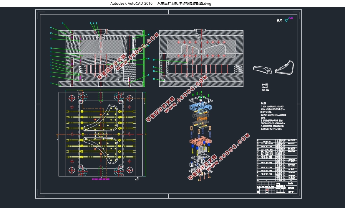
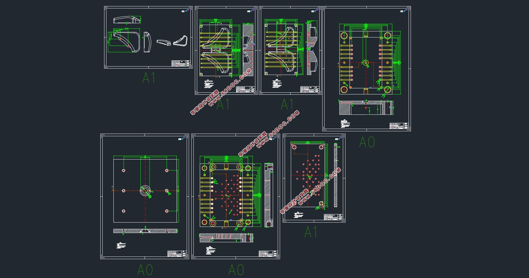
模具结构设计 针对模流分析的结果进行注塑模具的配套设计,包括注塑机的选择、浇注系统、冷却系统、成型零部件、结构零部件等设计,最后进行注塑模具装配图和非标准件零件图的CAD制图。
关键词:汽车后挡泥板;注塑模具;一模多腔;模流仿真分析;结构设计
Abstract
In this paper, based on NX10 for the automobile rear mudguard for a multi-cavity injection mold design, the automobile rear mudguard injection mold three-dimensional design and modeling, including the main channel, shunt, gate, cold Design of the casting system of the material and the pull rod; Design of the molding parts of the core and cavity; the selection of the standard mold base of the injection mold and the design of the structural parts of the directional mold design; the design of the push rod and so on; Flow channel and other temperature control system design. In addition, based on MOLDFLOW software, the injection molding process of the injection mold and the rationality of the mold structure were simulated and compared, and the different schemes were optimized and optimized. Injection molding mold injection time, flow front temperature, clamping force and other aspects of the check. The model of the plastic parts is divided into finite element meshes and the problems of the selection of the model materials, the establishment of the cooling pipes, the establishment of the pouring system, the analysis of the forming process, the setting of the analysis order and so on are carried out during the injection molding process. Flow + cooling analysis, adjust the plastic parts of the cooling structure.
Main content of this dissertation:
1.Analysis of moldflow: Using MOLDFLOW2015 simulation software, the optimal flow channel system and cooling system design are analyzed, and the gate size and runner size are optimized reasonably, instead of the actual test mode, which improves the design and production efficiency.
2.The design of structure of injection mold: For the results of mold flow analysis of the design of injection molds, including the choice of injection molding machine, casting system, cooling system, forming parts, structural parts and other design, and finally injection mold assembly drawings and non-standard parts CAD drawing.
Keywords:automobile rear mudguard; injection mold;design; multi-cavity; moldflow stimulation;structure design
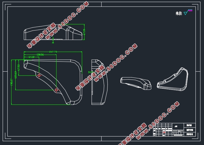
车后挡泥板的成性要求和塑件条件如形状结构、尺寸大小、精度等级和表面质量要进行仔细研究和分析,慎重考虑上述因素之后才能设计并且制造出合理的规范的注塑模具。
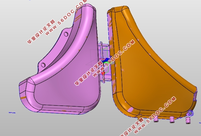
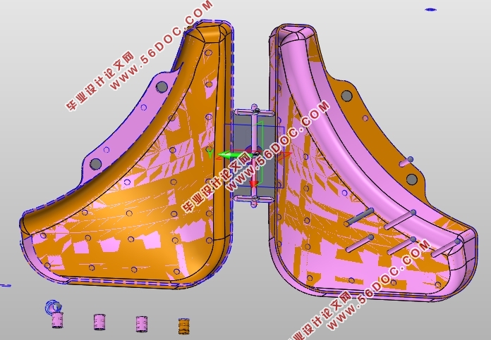
本次设计的目标是常用的汽车后挡泥板,其零件外形如图所示。具体结构和尺寸详见图纸,该塑件结构简单,生产量大,所以模具成本应该尽可能低,成型容易,精度和表面质量要求不高。
挡泥板产品造型3D视图
塑料件的尺寸精度直接关系到模具的结构设计以及制造过程中的精度。考虑到成本问题以及制造过程中的难度系数,我们需要在汽车后挡泥板使用条件允许的情况下尽可能地把塑件的精度等级设计得低。因为塑料和金属之间的差别非常明显,我们不能按照金属部件的公差水平来确定精度水平。根据任务书和绘图要求,本产品尺寸采用MT3级精度,不额外标注的使用MT3级精度。
塑料部件的表面要求越高,表面粗糙度越低。 除了从成型过程中尽可能避免冷疤,云纹等瑕疵确保,剩下的主要取决于模腔表面粗糙度。 塑料制品的表面粗糙度一般在Ra 0.02〜1.25之间,表面的表面粗糙度应为塑料件的1/2,即Ra为0.01〜0.63。 模具在使用过程中会因为使用额原因产生磨损,这种磨损会使得塑件成型的表面质量下降,所以在这时会对成型零部件进行模具抛光。在本次设计中,塑件的表面粗糙度为Ra0.8 ,内部为Ra1.2 。
目 录 0
摘 要 1
第1章 绪论 1
1.1意义,目的 1
1.2国内外的发展现状 1
1.3汽车后挡泥板的研究内容及其实验方案 2
1.3.1研究内容 2
1.3.2设计目标 3
1.3.3拟采用的技术方案以及措施 3
1.4 Moldflow2015 模流分析技术 4
1.5 小结 4
第2章 汽车后挡泥板塑件分析 6
2.1 汽车后挡泥板分析及其技术条件 6
2.2 汽车后挡泥板材料的确定 7
2.3 汽车后挡泥板材料的性能分析 7
2.3.1基本特性 7
2.3.2主要用途 7
2.4 小结 8
第3章 MOLDFLOW模拟成型分析 9
3.1 MOLDFLOW软件介绍 9
3.2 模型导入以及网格划分 9
3.2.1计算网格确定 10
3.3 充填时间分析 11
3.4 流动前沿温度分析 12
3.5 顶出时体积收缩率 12
3.6 锁模力的分析 13
3.7 冻结层因子分析 14
3.8 熔接线分析 15
3.9 变形量分析 16
3.10 小结 17
第4章 成型布局及注塑机选择 18
4.1 进料方式选择 18
4.2 型腔的布局及成型尺寸 18
4.3 测量塑件体积质量 19
4.4 注塑机的选择和校核 19
4.4.1锁模力的计算 19
4.4.2塑料熔体注射量的计算 20
4.4.3 模具与注射机安装模具部分相关尺寸校核 20
4.4.4 注塑机选择确定 22
4.5 小结 22
第5章 注塑模具设计 23
5.1 模具结构的详细设计 23
5.1.1模架基本类型 23
5.1.2模架的选择 23
5.1.3导向与定位机构设计 24
5.2 浇注系统的设计 25
5.2.1主流道设计 25
5.2.2分流道的设计 25
5.2.3浇口的设计 26
5.2.4冷料穴的设计 27
5.3 分型面的设计 27
5.4 成型零部件的设计 28
5.4.1 成型零部件的工作尺寸计算 28
5.4.2成型零部件结构 31
5.4.3推出机构 31
5.5 冷却系统的设计与计算 32
5.5.1冷却水道在定模和动模中的位置 32
5.5.2冷却水道的计算 33
5.6 排气结构设计 34
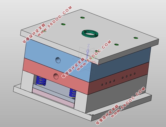
5.7总体结构的三维建模和爆炸图 34
5.8 小结 36
第6章 结论 37
致谢 39
附图 40
参考文献 42
|