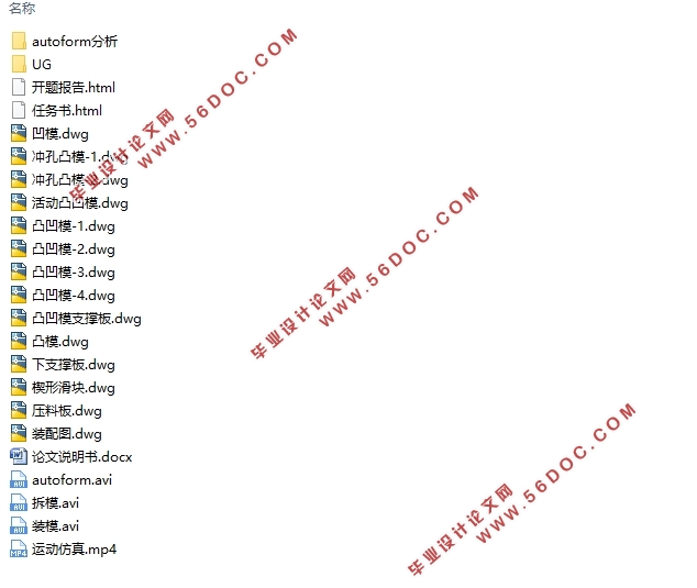
汽车连接件冲压模具设计及运动仿真(含CAD零件装配图,UG三维图)(任务书,开题报告,论文说明书15000字,CAD图14张,UG三维图,运动仿真)
摘要
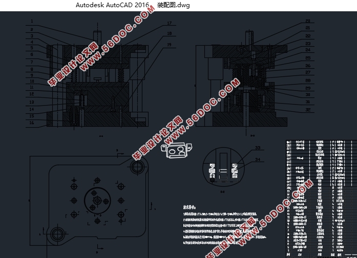
本文在运用AutoForm软件对汽车连接件冲压件成型过程进行应力分析的基础上完成汽车连接件冲压模具设计。利用UG软件进行模具三维零件图的建模并进行装配,然后用CAD绘制模具的二维装配图和零件图。模具设计完成后运用3Ds Max三维动画软件进行模具开合模运动过程的三维仿真。
在设计此套模具的过程中,本文的主要内容有:
1)在分析零件的形状、结构、精度和成型过程应力分析的基础上,完成汽车连接件冲压模具的总体方案设计。分析几种技术方案的可行性,比较单工序模、级进模和复合模的优劣,确定其最佳方案。针对其中较可行的复合模展开研究,同时完成相应的模具设计。
2)分析四面弯曲的成形特点,将弯曲件展开并测量其尺寸,以此为依据设计落料凸、凹模的结构和基本尺寸。另一方面,通过分析工件弯曲特点,设计凸凹模的结构。根据模具间隙对弯曲件质量、弯曲力和模具寿命等的影响,来确定间隙值的大小,计算凸、凹模的工作尺寸及公差。对凸、凹模等主要零部件进行了强度校核。
3) 其他零部件和标准件的设计和选型。
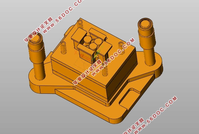
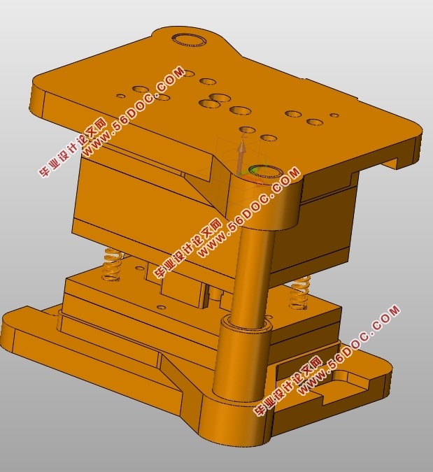
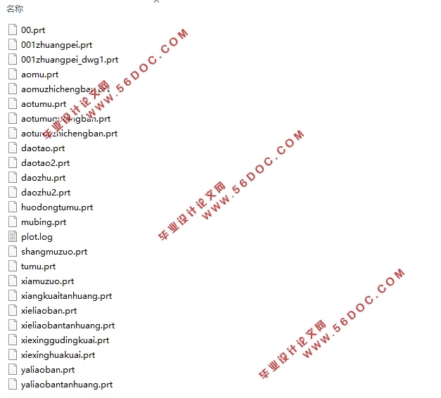
4)将UG建好的三维模型导入3Ds Max,进行零部件拆装和开合模运动仿真。
本文的创新点在于:在对零件结构工艺性和材料成型过程应力进行分析的基础上,合理安排其工序内容,巧妙地设计了一套专门针对该零件的集落料、弯曲、冲孔于一体的复合模。
关键词:冲压成型;应力分析;尺寸计算;运动仿真
Abstract
In this paper, it completes the design of stamping die for auto parts,based on the analysis of the stamping process of automobile connecting parts by using AutoForm software. Using UG software to carry on the modeling and assembly of 3D parts drawing, and then drawing the 2D assembly drawing and part drawing with CAD. After having finished designing the mold, 3Ds Max is used to do the motion simulation, which makes us know the motion of the mold in working clearly.
During the process of designing themould,the main contents of this paper are as follows:
1) Based on the analysis of the shape, structure, precision and forming process of the parts,I complete the overall scheme design of the stamping die for the automobile connecting parts .The feasibility of several technical schemes is analyzed, and the optimum scheme is determined by comparing the advantages and disadvantages of single working procedure, progressive die and compound mould. Researching on the more feasible compound mould, and at the same time to complete the corresponding mold design.
2)After the analysis of the forming characteristics of the four sides bending, calculating the length of bending part, based on which to design the blanking convex, concave die structure and the basic size. On the other hand, through the analysis of bending characteristics, designing the structure of punch and die. According to the influence of die clearance on the quality of bending parts, bending force and die life, to determine the size of the gap, to calculate the working dimensions and tolerances of convex and concave die. Checking the strength of the main parts such as Convex and concave die.
3)The design and selection of other parts and standard parts.
4)Importing the three-dimensional component finished by UG to 3Ds Max to conduct the opening and disassembling of parts, motion simulation of mold.
The innovative point lies inreasonably organizing its process contentwhich is based on the analysis of the structure forming process and material molding process stress, and cleverly designing a special compound die which combines theSet blanking, bending, punching of the part.
Key Words:stamping process; stress analysis; dimension calculation; motion simulation
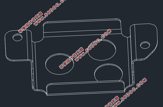
零件上有三个半径9mm大孔、两个半径3mm小孔冲孔完成。两侧二次折弯、前后折弯成型,与主体面成90度角。该零件厚度为1mm,零件形状不规则,由圆弧和直线组成,尺寸中等孔边距足够大,无尖角过渡,结构工艺性良好,根据上述零件特征适合采用冲压成形。
由于存在二次折弯,要求所用板料具有良好的塑性;应具有光洁平整且无缺陷损伤的表面状态。零件的材料为08A(碳钢),材料厚度为1mm。08AL是优质碳素结构钢的一种,塑性很好,退火或正火状态下垂直于轧制方向的最小弯曲半径为0.1t,即r_min=0.1 x 1=0.1mm。而零件的弯曲半径为r=1mm>0.1mm,在弯曲过程中不会出现弯裂,保证了足够的刚度和强度。
在冲压件的大中批量生产时,生产效率、材料利用率等可变成本以及模具使用寿命是决定冲压成本的关键因素。可以选用高生产率的复合模,及多工位的级进模,以及高寿命的硬质合金模具等。为降低可变资本,不得不提高模具制造的费用,但由于批量大,冲压件单件的成本还是降低了,可以获得很好的技术经济效益。
软件的分析过程为:读入零件几何模型(零件设计)、工艺规划、模面设计、定义毛坯料设计坯(料片设计)、仿真模拟、结果分析等
目 录
第1章绪论 1
1.1 课题研究的目的和意义 1
1.2 课题来源 1
1.3国内外的研究现状 1
第2章工艺性分析与工艺方案的确定 3
2.1 Autoform对零件的工艺性分析 3
2.1.1 Autoform工艺分析软件的介绍 3
2.1.2 Autoform对工件的工艺分析 3
2.2工艺方案的提出与确定 5
2.2.1工艺方案的提出 5
2.2.2工艺方案的确定 6
第3章复合模成形零部件设计 8
3.1 四角形弯曲 8
3.1.1 弯曲变形过程 8
3.1.2 弯曲件展开长度的计算 9
3.1.3 凸模、凹模结构 11
3.1.4 弯曲力的计算 12
3.2 冲裁工艺 13
3.2.1 冲裁间隙 13
3.2.2冲裁凸、凹模刃口尺寸计算 14
3.2.3冲裁力及及压力中心计算 15
3.2.4排样与搭边 17
第4章复合模零件的设计 19
4.1 落料凹模的设计 19
4.1.1 落料凹模的外形尺寸 19
4.1.2 凹模的固定方法 20
4.2 弯曲凸模即冲孔凸模的设计 20
4.3凸凹模的设计 21
4.3.1 凸凹模壁厚的确定 21
4.3.2 凸凹模长度的确定 21
4.3.3 凸凹模活动镶块 22
4.4卸料、压料部件的设计 23
4.5 其他零件的设计 23
4.5.1 垫板的选择 23
4.5.2固定板的选择 23
4.6 压力机和其他标准件的选择 23
4.6.1 压力机的选择 23
4.6.2 模架的选择 24
4.6.3模柄的选择 25
4.6.4螺钉与销钉 25
第5章工作过程及运动仿真 26
5.1工作过程 26
5.2运动仿真 27
5.2.1UG三维实体建模与装配 27
5.2.2开合模仿真动画 29
5.2.3模具拆装动画 29
第6章工程估价 29
第7章总结 31
参考文献 32
致谢 34
|