基于NX的仪器盒内抽芯模具设计(含CAD图,UG三维图)(论文说明书10000字,CAD图4张,UG三维图)
摘 要
由于当今对科技的要求逐日增强,对零件的结构性能是一大考验,这激发了模具行业中模具设计向着更复杂、更精密的方向发展。早在很久之前,在普通的零件上就常有一些斜槽或者内扣等技术要求较高的部分,对于这一情况需要借助内抽芯机构或者其他方式,使零件达到技术要求。
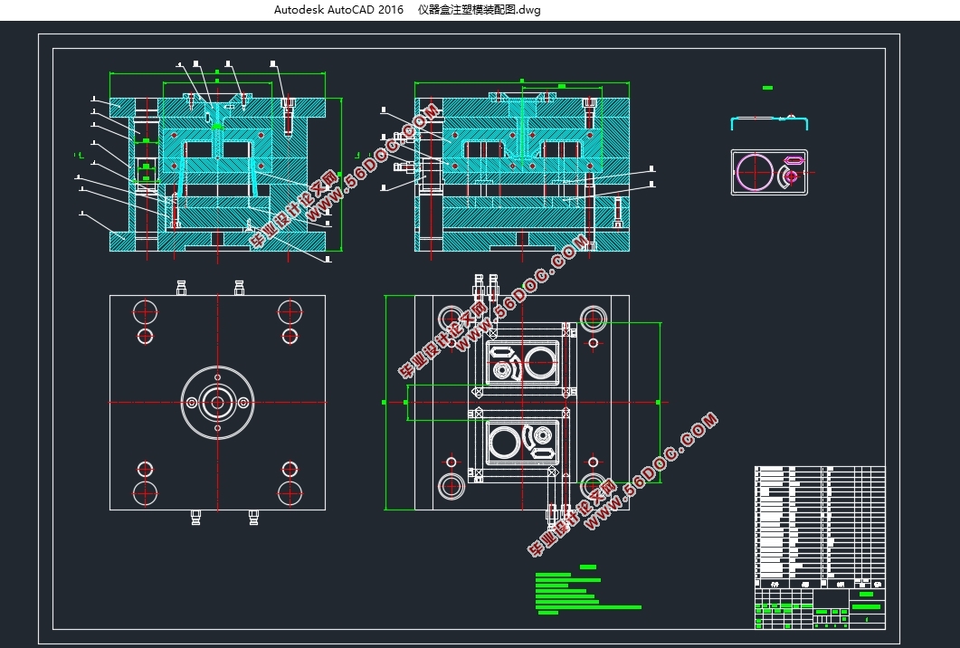
本设计的主要任务是基于NX的仪器盒内抽芯模具设计,详细来讲模具结构为一模二腔的一次分型打开的两板式模具。模具中设计了一种特殊的内置式抽芯机构,因为零件的内壁上存在有一个内扣结构,必须增加有内抽芯机构才能满足结构性要求,但是这个内抽芯结构的加入大大增加了该机构的复杂度。该设计通过借助NX6.0 moldwizard 模块进行模具设计,鉴于本论文研究的是仪器盒内内抽芯模具是设计,零件的大概轮廓以面壳类零件为主,先是借助NX6.0软件设计出零件的图纸,再在注塑模导向模板分别进行凸凹模、模架、浇注系统和冷却系统等方面的设计。
因为不同版本的UGNX模块系统有些许不同,本文还将针对NX6.0系统进行详细的步骤分析,与此同时在设计中考虑到实际产品的质量要求和工艺要求,给出了合理且可行的设计方案,抽芯机构、推杆等在模具中的布置问题都考虑在了设计过程中。
总之,此设计是结合了在校期间所学的知识,再结合长期学习积累的经验,借助UGNX6软件进行模具设计。
关键词:模具设计;内抽芯;抽芯机构;注塑模
Abstract
As the requirement of science and technology is increasing day by day, the structural performance of parts is a big test, which stimulates the mold design in the mold industry to develop towards more complex and more precise direction.As early as a long time ago, there were some parts with high technical requirements, such as chute or reverse buckle, on the common parts. For this situation, it is necessary to use the internal core pulling mechanism or other ways to make the parts meet the technical requirements.
The main task of the design is based on the first mock exam of the NX instrument box, and the die structure is two die with one mold and two cavities.A special built-in core pulling mechanism is designed in the die, because there is a reverse buckle structure on the inner wall of the part,The internal core pulling mechanism must be added to meet the structural requirements, but the addition of the internal core pulling structure greatly increases the complexity of the mechanism.This design is based on nx6.0 Moldwizard module. In view of the fact that this paper studies the design of the core pulling mold in the instrument box, the general outline of the parts is mainly the surface and shell parts,First, the part drawing is designed with nx6.0 software, and then the convex and concave mold, mold base, pouring system and cooling system are designed in the injection mold guide template.
Because different versions of UGNX module system are slightly different, this paper will also carry out detailed step analysis for nx6.0 system, at the same time, considering the quality requirements and process requirements of actual products in the design, give a reasonable and feasible design scheme, and the layout of core pulling mechanism, push rod and other issues in the mold are considered in the design process.
In a word, this design is a combination of the knowledge learned in school, combined with long-term learning experience, with the help of ugnx6 software for mold design.
Key Word:Mould design; Inner core pulling; Core pulling mechanism; Injection mold
塑件结构分析
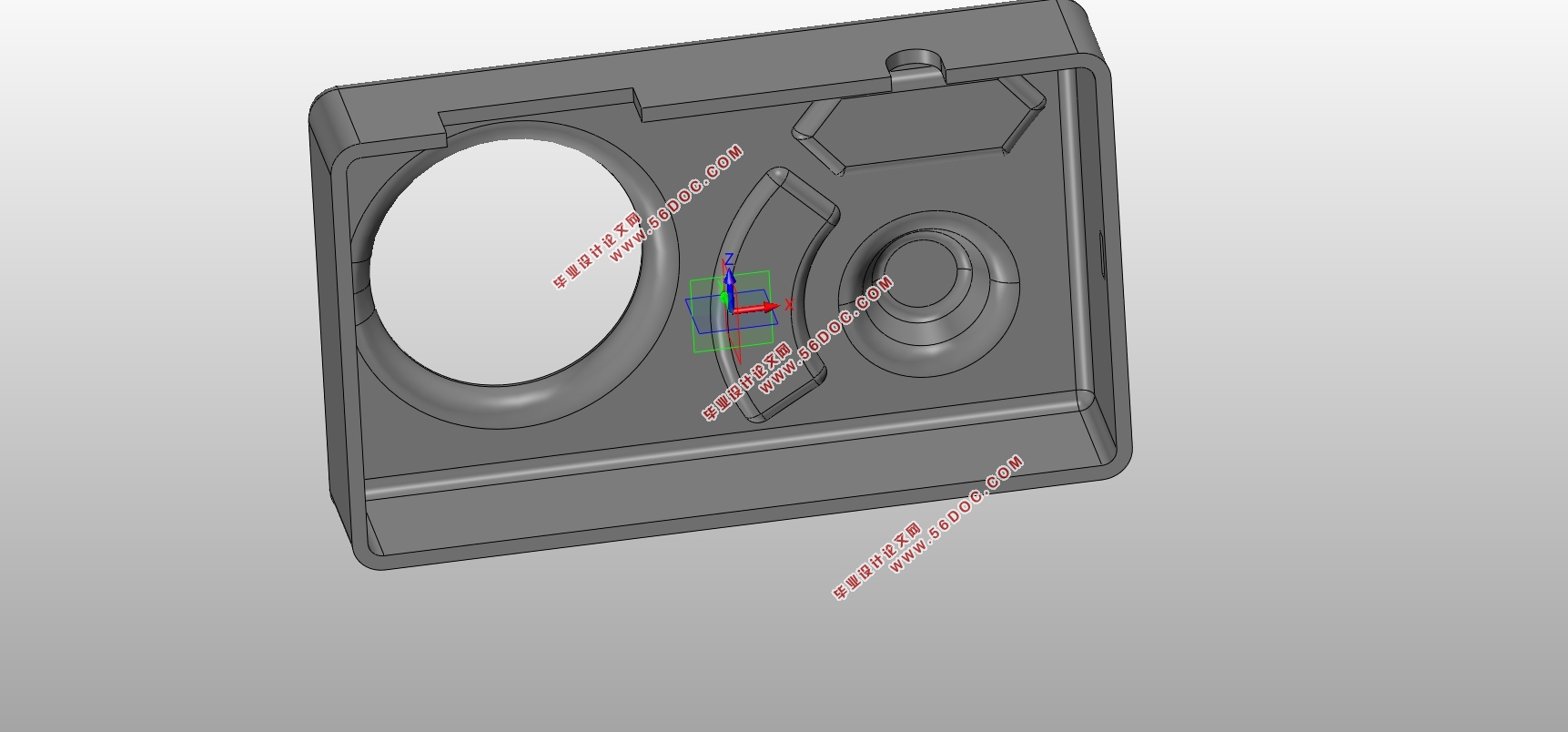
本课题研究的是一个面壳类零件,也是最为最为典型的内抽芯模具,也就是仪器盒。在其内壁上有两个小内扣,在这种情况下必须进行内抽芯操作才能保证基本的工艺要求,但于此同时,因为内抽芯结构的存在使得模具的设计变得复杂多了。
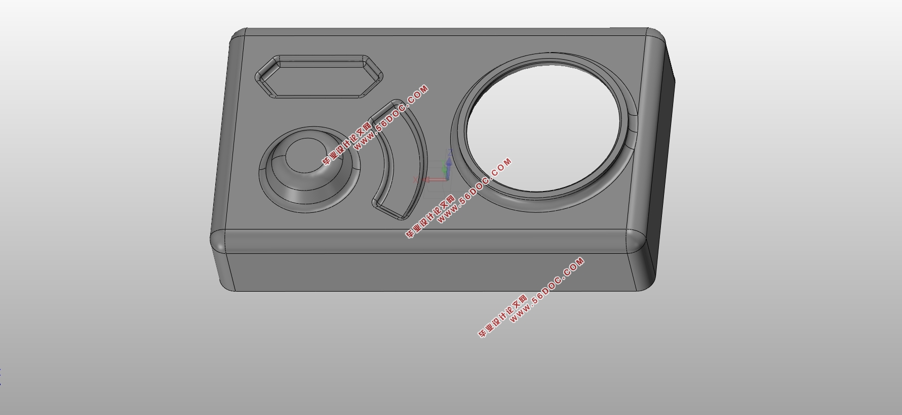
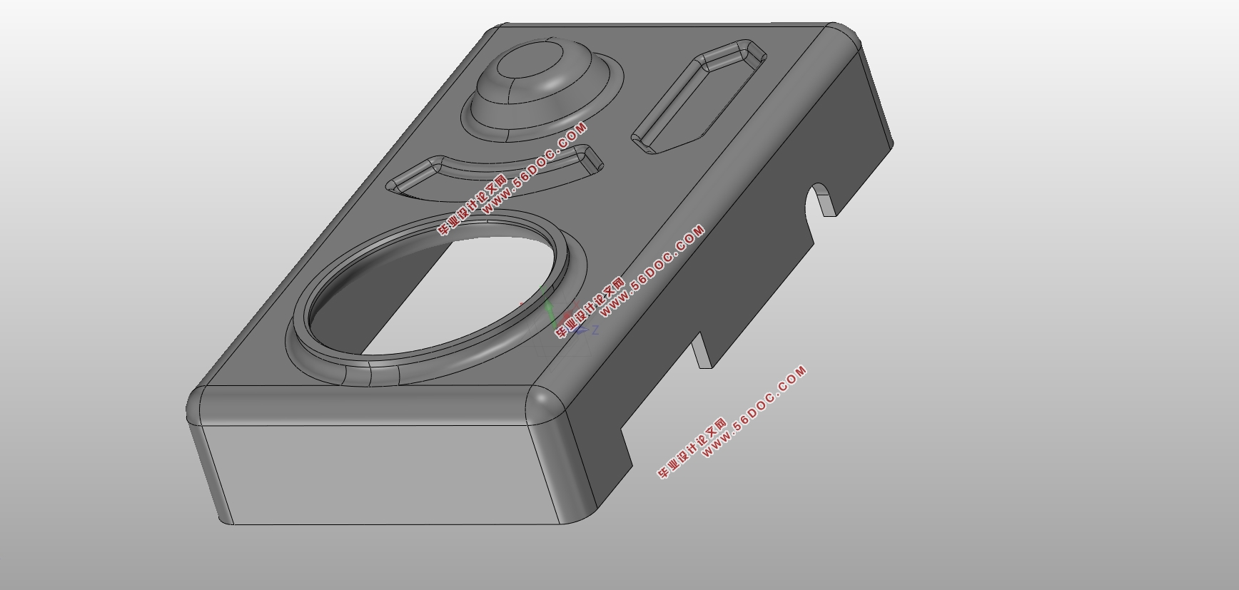
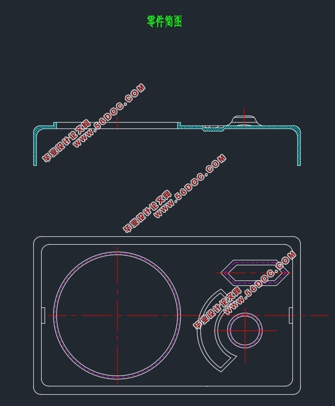
从塑件的外形上来分析,最大的外形尺寸是100mm×60mm×20mm,粗略的估概来看,塑件的体积有120cm3左右,其壁厚约为2mm。从如下2-1图所示,塑件的左部分具有一个Φ39mm的大圆台,而且有Φ35mm的通孔,在右边有一个直径为10mm的凸圆台,另外有两个形状规则的凹槽,每个形状的边框都做了边倒圆的命令。另外,在零件的内壁有两个内扣结构,因为内扣的存在,加大了设计的难度,需要借助内抽芯机构来实现它的工艺要求,如图2-2图所示,较为鲜明地展现了内扣的具体位置。此零件所用的材料是ABS,收缩率1.005,之所以选用ABS材料,是综合了很多方面考虑的。比如说考虑零件的质量要求、技术要求以及是否有特殊加工方式。

目 录
第一章 绪论 1
1.1. 本文研究的背景 1
1.2. 模具产业国内外发展及国内技术性发展趋势分析 2
第二章 本课题研究内容及可行性分析 4
2.1. 塑件结构分析 4
2.2. 选用ABS材料的原因分析 5
2.3. 脱模难点分析 5
2.4. 设计方案的拟定 5
第三章 模具结构设计 7
3.1. 注塑模设计预处理 7
3.2注塑模具体设计过程 8
3.3添加内抽芯及标准部件 11
3.4浇注系统设计 13
3.5冷却系统设计 13
3.6模具设计最终确定 14
第四章 模具开模的运动仿真 16
4.1进行运动仿真的目的 16
4.2运动仿真的实现 16
4.3开始运动仿真 17
4.4创建运动动画 18
第五章 模具结构稳定性分析 20
5.1模具装配图结构分析 20
5.2内滑块设计的注意要点 20
5.3其他结构分析 20
5.4二维分析及设计总结 22
5.4.2模具爆炸图 22
5.4.3仪器盒内抽芯模具设计总结 23
5.5仪器盒注塑模具的部分零件图 23
结束语 26
致 谢 27
参考文献 28
|


