分油器壳体注塑模具设计(含CAD零件图装配图)(选题审核表,任务书,开题报告,外文翻译,论文说明书12000字,CAD图16张)
DESIGN OF INJECTION MOLD FOR OILSEPARATOR SHELL
摘要
在科技发达的今天,注塑模具发挥了重要的作用,在机械、器械、生产、用品的产品中都存在并使用注塑模具的生产。从模具被使用到至今模具设计和制造也是不断的进步与创新,以前绘制装配图和零件图都是用手绘现如今科技发达绘制图纸只需要用电脑绘图软件进行绘制,不仅仅绘制二维装配图连三维也能绘制。
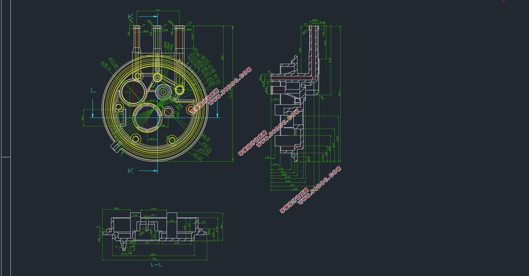
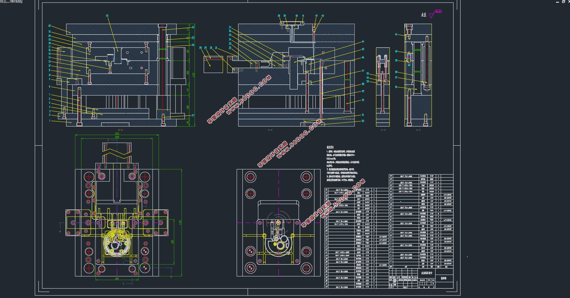
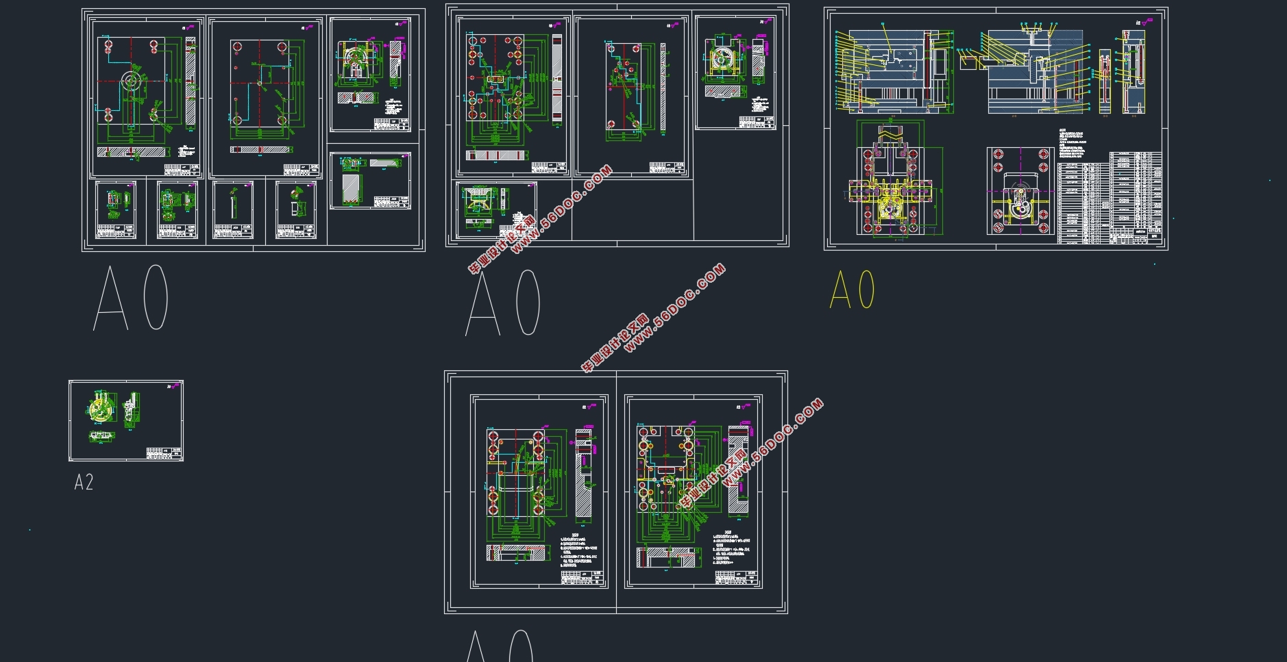
本次设计是设计分油器壳体注塑模具为设计任务,分油器外形光滑而且简单,用三维软件绘制产品即可。在绘制过程中要考虑到抜模的斜度,以便于顶出脱模。绘制完成后,根据产品需求排列出一模一腔计算出它的模架,然后再确定它的分型面。分型面的选择也要考虑到脱模的方向和零件的外形,而且还要考虑到型芯和型腔的机械加工方便性和顶出机构的受力均匀。根据产品的排列和原料的流动性收缩率选择进料口使其填充面不缺料。冷却方法是根据模具的设计产品的摆放来确定,一般情况采用环绕式的水管。推出机构通常采用圆顶针设计,这种圆顶针的推模方式会留下顶出痕迹,如不希望留下顶出痕迹可使用推板推出或者使用机型手取出等结构,选用的方式根据产品的使用和外观要求而定。三维软件绘制完成后根据绘制后的图形再使用CAD绘制二维装配图和零件图,这样绘制二维装配图时会更加方便不容易出现错误。在设计过程中需考虑到模具在机械加工方面的制造工艺,还有就是需要考虑在制造完成后模具使用的安全设备在维修方面更加方便更换宜受损部分的零件,这都是在设计过程不可缺少的。
关键词:注塑模具、三维软件、机械、模具设计、CAD
Abstract
Today, with the development of science and technology, injection mold plays a significant role in the production of machinery, equipment and supplies. Since the creation of the mould, the mould design and manufacture have also made continuous progress and innovation. In the past, the assembly drawings were drawn by hand. Now, the advanced technology only needs computer to draw the drawings, not only two-dimensional assembly drawings but also three-dimensional drawings.
The reference part of this design is to take the oil separator shell as the design task. The product is smooth and simple in shape, and the product is drawn with UG 3D software. In the process of drawing, the angle of mould should be taken into account to facilitate ejection and demoulding. After drawing, the first mock exam is arranged according to the requirement, and the mould surface is calculated, and the analysis surface is determined. The selection of parting surface should also take into account the direction of demoulding and the shape of the parts, as well as the convenience of machining the core cavity and the uniform force of the ejection mechanism. According to the arrangement of products and the flow shrinkage of raw materials, the feeding port is selected so that the filling surface is free of material shortage. The cooling method is determined according to the placement of the designed products of the mold, generally using the surrounding water pipe. The ejector mechanism usually adopts a round top needle, which will leave a ejection trace. If there is no ejection trace, the ejector plate can be used to push it out or the machine hand can be used to take it out. The selection method depends on the use and appearance requirements of the product. After three-dimensional software drawing is completed, two-dimensional assembly drawing and part drawing are drawn by CAD according to the drawing, so that the thinking of drawing two-dimensional assembly drawing is clear and not easy to make mistakes. In the design process, it is necessary to take into account the manufacturing process of the die in terms of machining, as well as the convenience of maintenance and replacement of the safety equipment used in the die after the completion of manufacturing, which are indispensable in the design process.
Key words: injection mold, UG, machinery, mold design, CAD
塑件的工艺分析
塑件的原料有合成的和天然的高分子化合物,使用条件是在高温下熔融塑化,使用注塑机注射在模具型腔内成型。在注塑生产时注塑材料的熔融温度大约是210到320℃,符合注塑生产的特性,当熔料的温度超过260℃时注塑材料就会发生分解。根据使用要求本次采用ABS注塑原料,此注塑原料为高分子化合物由晶体组成,具有一定的强度和耐冲性能、还有良好的热学性能。ABS注塑冷却成型后表面光滑,可以进行染色、电镀等。大部分原料都是根据产品的使用要求来选定的一般都会选择无毒无气味的原料,ABS的填充性能很好,使用较为广泛,最重要的是能节约生产成本,对环境也无污染。


目录
摘要 I
Abstract II
第一章概述 1
1.1模具的地位 1
1.2模具的发展 2
1.3注塑模具的重要性 3
1.4课题需要解决的问题 3
1.5设计思路 4
第二章 塑件工艺和材料分析 5
2.1 塑件结构分析 5
2.2 塑件的工艺分析 5
2.3计算塑件的体积和质量 6
2.4分型面的选择 7
2.5塑料成型设备的选取 8
第三章 模具结构方案的确定 10
3.1 出模数量与型腔布局 10
3.2 型腔出模数量的校核 10
3.3、浇注系统设计 11
3.3.1 浇注系统 11
3.3.2 主流道的设计 11
3.3.3 分流道的设计 12
3.3.4 浇口的设计 13
3.3.5 冷料穴的设计 13
3.4 排气机构的设计 14
3.5脱模机构设计 14
3.5.1脱模力的计算 15
3.5.2推杆强度的校核 15
3.6复位机构设计 16
3.7模架系统设计 16
第四章、成型零件结构设计 18
4.1成型零件的设计 18
4.2、型腔结构设计 18
4.3、型芯结构设计 18
4.4 成型尺寸计算 19
4.4.1 型腔成型零件尺寸计算 19
4.4.2 型芯成型零件尺寸计算 20
4.4.3型腔零件的强度刚度校核 21
4.5 成型零件钢材的选用 21
第五章、模具冷却系统设计 22
5.1、冷却系统概述 22
5.2、冷却水道的计算 22
5.2.1求塑料制品在固化时每小时释放的热量Q 22
5.2.2 水的体积流量 23
5.2.3 求冷却水道直径d 23
第六章 注塑机的选择与校核 25
6.1 注塑机的工作原理 25
6.2 注塑机注射容量的校核 25
6.3 校核压力 25
6.4 校核模具安装尺寸 25
6.5校核移模行程 26
6.6 校核注塑机锁模力 26
第七章 抽芯机构的设计 27
7.1 抽芯机构的概述 27
7.2 抽芯机构的计算 27
第八章、绘制模具总装图 29
8.1、本模具总装图 29
总结 30
致谢 31
参考文献 32
|


