Φ40×12电器盖注塑模具设计(含CAD零件装配图)(任务书,设计说明书12000字,CAD图纸12张)
摘 要
随着经济的发展和人们生活水平的提高,对一些小的物品就像一个小小的按钮都有独到的要求,不仅要方便使用而且对外观的要求也很高.所以对塑料模具的要求也很高也越来与越高。随着现代工业发展的需要,模具是重要的工艺装备之一,它在工农业生产以及日常生活中得到了广泛的应用。由于采用模具进行生产能提高生产效率、节约原材料、降低成本,并可保证一定的加工质量要求,所以在电子,汽车、电机、电器、飞机、仪表,家电和通讯等产品中大部分零部件都采用模具进行加工。塑料模具设计则是模具的主要部分,塑料模具的设计与制造水平的普及提高,是塑料成型加工工业,发展必不可少的重要条件.模具生产技术水平的高低,已成为衡量一个国家产品制造水平高低的重要标志.此次,通过对端盖注塑模具的设计,可以使我对注塑模有更深刻的理解而且可以熟练掌握相关软件,同时也锻炼了我综合运用所学知识解决实际问题的能力。.
对于塑料模具来说,目前市场上的百分之九九的外壳类产品都采用塑料,因为它不用承受很大的负载,塑料又起到了绝缘的效果.塑料的颜色多变,能满足人们不同的喜好。
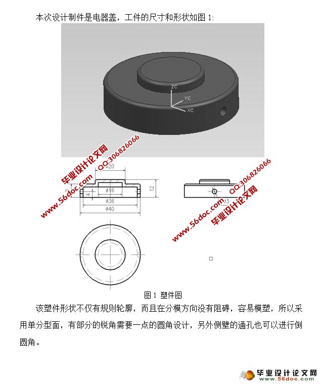
本次设计的是的电器盖注塑模具设计,分析可知该零件的外形比较小,因此采用浇注系统为侧浇口模式,一个模具两个型腔,单分型面注射成为本次设计的结构模式。本次设计的具体操作如下:首先是对于本次所要设计的塑件进行一系列的分析。其中包括了对塑件结构的尺寸分析和材料分析。然后是是对本次设计的塑件设计一个合理的方案。其中包括了分型面的确定,型腔数量的确定以及浇注系统和顶出系统的设计。
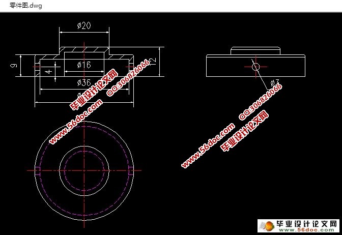
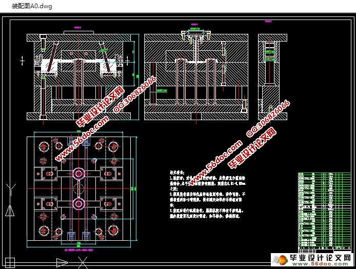
对于该模具的设计,先要选定一台符合本次设计要求的注塑机。然后是设计该塑件的浇注系统。接着是对成型零部件的结构设计和工作尺寸的计算。以及对排气系统和冷却系统的优化。最后是对于整个模具的装配的要求和过程,并且使用CAD软件绘制了本次设计的模具的装配图和各个零件图。总结了设计说明书。
关键字:注塑模具;侧浇口;CAD。
Abstract
With the economic development and people's living standards improve, on a number of small items like a small button has unique requirements, should not only has the advantages of convenient use and appearance requirements are very high. So the requirement of plastic mold is also very high and and higher.
With the development of modern industry, the mold is one of the important technological equipment, it has been widely used in industrial and agricultural production and daily life.Home appliances and communication products such as most of the parts of the mold processing. Plastic mold design is the mold of the main part, improve the popularity of the plastic mold design and manufacturing level, plastics processing industry, essential for the development of an important condition. Level of mold production technical level has become the measure of a national product manufacture level of an important symbol of. This time, by the end cover injection mold design can enable me to cast the mold to have more profound understanding and mastery of the relevant software, but also exercise the integrated use of my knowledge to solve practical problems.
For plastic mould, at present market of 99 percent of shell products are made of plastic, because it doesn't have to bear great load, plastic and insulation. Plastic color changeable, meet people's different preferences.
This design is the electrical cover injection mold design and analysis shows that the parts of the shape is relatively small, so the use of gating system for side gate pattern and a mold two cavity, a single type of injection into the design modes of the structure. The design of the specific operation are as follows: first, the design of the plastic parts to carry out a series of analysis. The dimension analysis and material analysis of the structure of the plastic parts are included. Then is the design of the plastic parts of the design of a reasonable solution. It includes the determination of the parting surface, the determination of the number of cavities and the design of the gating system and the ejection system.
For the design of the mold, we must first select a machine that meets the requirements of the design of the injection molding machine. Then the casting system of the plastic part is designed. Then the structure design of the forming parts and the calculation of the working dimensions are followed. Optimization of exhaust system and cooling system. Finally, the requirements and process for the entire mold assembly, and the use of CAD software to draw the design of the mold assembly drawing and parts drawing. The design specification is summarized.
Keywords: injection mold side gate; CAD.
目 录
第1章.绪论 1
第2章 塑料制件的分析 2
2.1 成型塑料件的工艺性分析 2
2.2 成型塑件的材料分析 3
第3章 注塑设备的选择 4
3.1估算塑件体积质量 4
3.2 注塑机的选择 4
第4章 成型零件设计和计算 6
4.1凸模的结构设计 6
4.2凹模的结构设计 7
4.3 型芯型腔尺寸计算 8
4.3.1型腔凹模尺寸的计算 10
4.3.2型芯凸模尺寸的计算 12
第5章 浇注系统的设计 14
5.1 分型面的选取 14
5.2模具型腔排列方式 16
5.3浇口套的选用 17
5.4冷料井的设计 19
5.5分流道的设计 20
5.7浇口设计 22
第6章 合模导向机构的设计 23
6.1导柱的设计 23
6.2 导套的设计 25
第7章 脱模结构的设计 26
7.1 脱模力的计算 26
7.2推出结构的设计 27
第8章 侧向分型和抽芯机构的设计 29
8.1抽拔距的计算 29
8.2斜导柱的尺寸与安装形式 29
8.3 锁紧楔形式 31
8.4 斜导柱的受力分析及强度计算 31
第9章 排气系统和冷却系统的设计 32
9.1排气系统 32
9.2冷却系统的设计 32
第10章 绘制装配图 34
第11章 注射机的校核 36
11.1 注射量的校核 36
11.2 锁模力的校核 36
11.3 模具高度校核 37
11.4 模具开模行程校核 37
结论……….38
参考文献 39
致谢 40
|
