侧板连续式复合模设计(冲孔、落料、弯曲一体)(CAD,solidworks三
来源:wenku7.com 资料编号:WK710860 资料等级:★★★★★ %E8%B5%84%E6%96%99%E7%BC%96%E5%8F%B7%EF%BC%9AWK710860
以下是资料介绍,如需要完整的请充值下载。
1.无需注册登录,支付后按照提示操作即可获取该资料.
2.资料以网页介绍的为准,下载后不会有水印.资料仅供学习参考之用. 密 保 惠 帮助
资料介绍
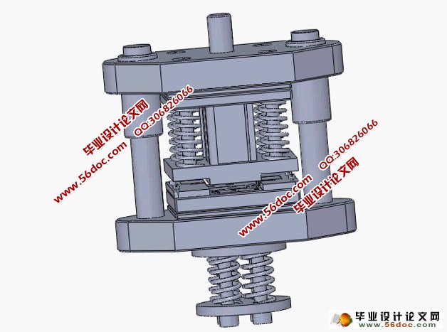
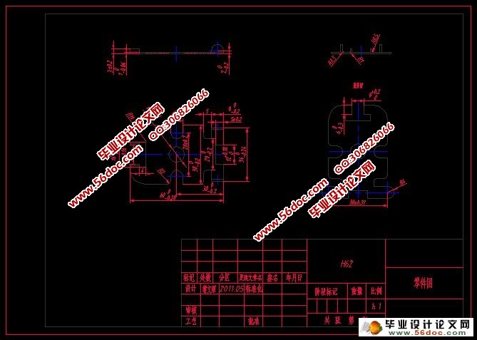
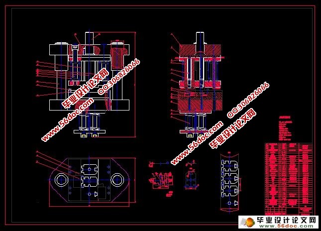
侧板连续式复合模设计(冲孔,落料,弯曲一体)(CAD,solidworks三维)(开题报告,中期检查表,论文说明书12200字,CAD图纸7张,solidworks三维)
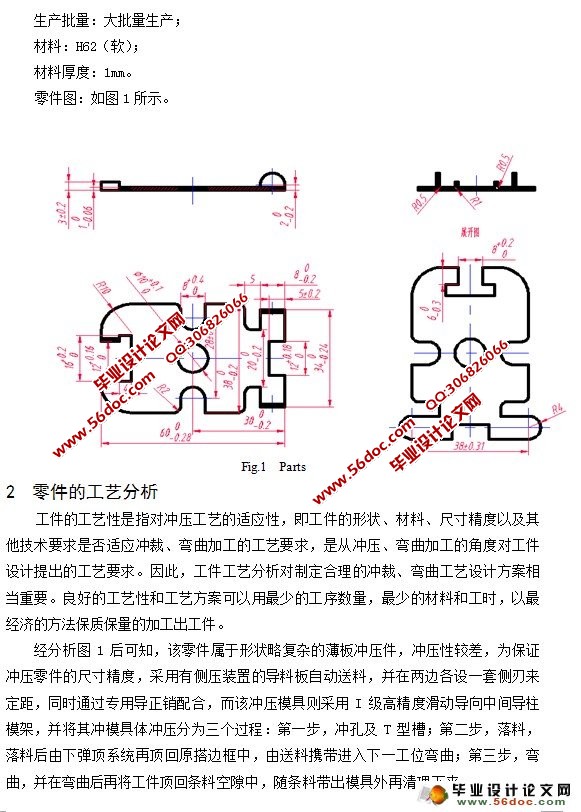
摘 要:冲压模具在实际工业生产中应用非常广泛,采用模具生产制品及零件,是现在工业生产的重要手段和主要发展方向。本次设计由于零件采用H62软态材料,冲压性较差,且为料厚1mm、冲压形状略微复杂的薄板冲压件,经过仔细分析零件的冲压工艺,并根据冲压工艺特性设计出了一套冲孔、落料、弯曲一体的侧板连续式复合模。
关键词:冲压工艺;冲压模具;结构设计
Design of Lateral Plate Continuous Type Compound Mould
Abstract:Blunt press a molding tool an application is extensive in the physically industrial production, and now the mold of production products and parts is an important means of industrial production and the main development direction. Because the parts has adopted H62 of soft state materials,the thickness of the parts is just 1mm, and the stamping is the plate stamping which is slightly complex, so the character of stamping is not good . After having analysised of the process of stamping ,according to that , then I have designed a lateral plate continuous type compound mould which can punch, blank and bend.
Key words:stamping process;stamping die;structural design
目 录
摘 要 1
关键词 1
前言 1
1 设计条件 2
2 零件的工艺分析 2
3 排样 3
4 计算冲裁、弯曲工艺力 4
4.1 弯曲力 4
4.2 冲裁力 4
4.2.1 冲孔冲裁力 5
4.2.2 冲T型槽冲裁力 5
4.2.3 落料冲裁力 5
4.2.4 卸料力 5
4.2.5 顶件力 5
4.2.6 总冲压力 5
5 计算模具压力中心 5
6 计算凸凹模尺寸 5
6.1 计算冲裁模尺寸 6
6.1.1 计算冲孔及T型槽凸凹模尺寸 7
6.1.2 计算落料凸凹模尺寸 7
6.2 计算弯曲凸凹模尺寸 9
6.2.1 计算凸、凹模间隙 9
6.2.2 计算凸、凹模宽度尺寸 9
6.2.3 凸、凹模的圆角半径与弯曲凹模的深度 9
7 定位零件 9
7.1 导料板 10
7.2 侧刃 10
7.3 导正销 11
8 卸料板 11
8.1 确定卸料板尺寸 11
9 顶件装置 11
10 固定零件 12
10.1 上、下模座 12
10.2 模柄 12
10.3 凸模固定板 13
10.4 垫板 15
11 弹簧 16
11.1 选取要求 16
11.2 顶件弹簧 16
11.3 卸料弹簧 17
12 导向零件 17
13 紧固及其他零件 18
14 模具装配工艺过程及总体结构 18
14.1 模具装配工艺过程 18
14.2 模具总体结构 19
15 压力机 20
结论 21
参考文献 22
致谢 23
|
