钢筋调直机设计(含cad零件图和装配图)(开题报告,中期检查报告,毕业论文11000字,cad图纸6张)
摘 要
伴随着建筑业的发展,建筑机械成为现代工业与民用建筑施工与生产过程中不可缺少的设备。建筑生产与施工过程实现机械化、自动化、降低施工现场人员的劳动强度、提高劳动生产率以及降低生产施工成本,为建筑业的发展奠定了坚实的基础。由于建筑机械能够为建筑业提供必要的技术设备,因此成为衡量建筑业生产力水平的一个重要标志,并且为确保工程质量、降低工程造价、提高经济效益、社会效益与加快工程建设速度提供了重要的手段。因此,对建筑机械的设计和研究具有十分重要的意义。
本文对钢筋调直机的设计进行了比较系统的研究,对钢筋调直机进行了分类和综合的介绍;对钢筋调直机的控制系统进行了概述;对钢筋调直机的工作原理进行了系统的分析;对钢筋调直机的功率计算与分配、受力分析、结构设计、主要零部件设计与选择等进行了详细的介绍。结合实际生产的需要,对产品总体结构和工作性能进行了优化设计,达到了比较完善的设计要求,最后对钢筋调直机进行了总体调试。
本次设计的钢筋调直机为电机驱动下切剪刀式钢筋调直机,用于调直直径为14mm以下的盘圆钢筋或冷拔钢筋。并且根据需要长度进行自动调直和切断,调直过程中将钢筋表面氧化皮、铁锈和污物除掉。充分发挥了其良好的机动性,体积小,操作简单,效率高等特点,在提高施工速度,保证施工质量的同时,降低了人工与材料的成本,减轻了劳动强度,提高了劳动生产率。
关键词:钢筋调直机;建筑;机械;施工
Abstract
Along with the development of the construction industry, construction machinery become indispensable in modern industrial and civil construction and production process equipment. Mechanization and automation of building production and construction process to reduce the labor intensity of construction site, to improve labor productivity, and reduce the cost of production and construction, has laid a solid foundation for the development of the construction industry. Construction machinery to provide the necessary technical equipment for the construction industry has therefore become an important indicator to measure construction productivity levels, and ensure project quality, reduce project cost, and improve economic efficiency and social benefits and speed up the construction speed provides an important means. Therefore, the design and construction machinery has great significance.
In this paper, the design of reinforced Straightening Machine System, classification and comprehensive introduction of reinforced Straightening Machine; an overview of the Bar Straightening Machine Control System; Bar Straightening Machine works carried outsystem analysis; power calculation and allocation of reinforced Straightening Machine, stress analysis, structural design, design of main components and the choice of detail. Combined with the actual production needs, the product of the overall structure and performance optimized design to achieve design requirements, the final overall debugging Bar Straightening Machine.
The design of reinforced Straightening Machine for a motor-driven cutting scissors reinforced Straightening Machine for Straightening diameter less than 14mm coiled steel or cold drawn steel bar. Automatic straightening and cutting off the required length, the straightening process will be reinforced surface oxide, rust and dirt to get rid of. Give full play to its mobility, small size, simple operation, high efficiency, and improve the speed of construction to ensure construction quality at the same time, reduces labor and materials costs, reduce labor intensity and improve labor productivity.
Key words: Steel Bar Straightening machine; building; machinery; construction
研究方案及预期结果
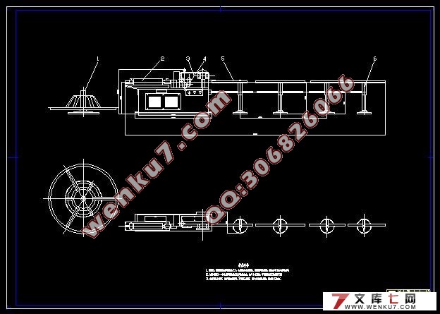
GT4-8型钢筋调直机为切刀断料式,主要由调直筒、传动箱、切断机构、承受架、及机座等组成,能够调直切断直径为4—8㎜的钢筋,钢筋抗拉强度650MPa,切断长度为300-6000㎜,切断长度误差≤3,牵引速度为40m/min,调直筒转速为2800r/min,送料、牵引辊直径为90㎜,调直、牵引与切断电机型号为JO2-42-4型,调直、牵引与切断功率为5.5KW,外形尺寸长×宽×高为7250㎜×600㎜×1220㎜,整机重量为1000Kg。
调直过程:钢筋经导向筒进入调直筒,调直筒内装有五个不在同一中心线上的调直块,钢筋在每个调直块的中孔中穿过,由上、下牵引轮夹紧后向前送进,穿过切断机构到受料槽中,调直筒以高速旋转,调直块反复的连续弯曲钢筋,将钢筋调直,同时清除钢筋表面的污物。
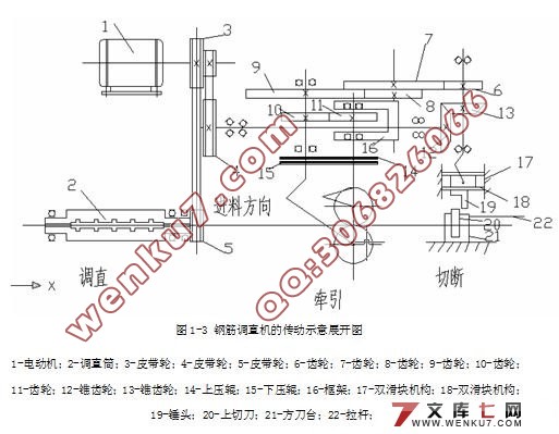
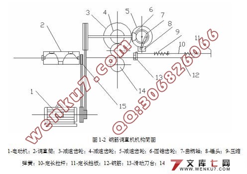
传动系统:电动机通过三角胶带传动装置带动调直筒旋转而进行调直工作。经电动机上的另一胶带轮以及一对锥齿轮带动偏心轴,再经二级齿轮减速,驱动上下压辊等速反向旋转,从而实现钢筋牵引运动。又经过偏心轴和双滑块机构,带动锤头上下运动,当上切刀进入锤头下面时即受到锤头敲击,完成钢筋切断。
切断机构主要由曲柄轮、连杆、锤头、定长拉杆、复位弹簧、刀台座、上切刀、下切刀、上切刀架组成。
电器线路主要由熔断器、交流接触器、热继电器、常开按钮、电动机、转换开关等组成。


目 录
前 言 1
第一章 钢筋调直机的设计 2
1.1 钢筋调直机的分类 2
1.2 钢筋调直切断机的构造及概述 2
1.3 钢筋调直机调直剪切原理 3
1.4 钢筋调直机工作原理与基本构造 4
1.5 钢筋调直机的主要技术性能 7
第二章 主要计算 8
2.1 生产率和功率计算 8
2.1.1 生产率计算 8
2.1.2 功率计算,选择电动机 8
2.2 第一组皮带传动机构的设计 12
2.2.1 确定设计功率 12
2.2.2 初选带的型号 12
2.2.3 确定带轮的基准直径 12
2.2.4 确定中心距和带的基准长度 13
2.2.5 验算小轮包角 13
2.2.6 计算带的根数 13
2.2.7 计算带作用在轴上的载荷 14
2.3 第二组皮带传动机构的设计 14
2.3.1 确定设计功率 14
2.3.2 初选带的型号 15
2.3.3 确定带轮的基准直径 15
2.3.4 确定中心距和带的基准长度 15
2.3.5 验算小轮包角 16
2.3.6 计算带的根数 16
2.3.7 计算带作用在轴上的载荷 16
2.3.8 主动带轮设计 17
第三章 直齿轮设计 18
3.1 确定齿轮传动精度等级 18
3.1.2 按齿面接触疲劳强度确定中心距 19
3.1.3 验算齿面接触疲劳强度 20
3.1.4 验算齿根弯曲疲劳强度 20
3.1.5 齿轮主要参数和几何尺寸 21
第四章 锥齿轮设计 23
第五章 轴的设计与强度校核 28
5.1 I轴的设计与强度校核 28
5.1.1 轴的结构设计 28
5.1.2 求出齿轮受力 28
5.2 Ⅱ轴的设计与强度校核 30
5.2.1 轴的结构设计 30
5.2.2 求出齿轮受力 30
第六章 主要零件的规格及加工要求 34
6.1 调直筒及调直块 34
6.2 齿轮 34
6.3 传送压辊的选用和调整 34
6.4 调直机的各传动轴均安装滚动轴承 35
6.5 定长机构的选择与调整 35
结 论 36
致 谢 37
参考文献 38
|


