CA6140机床主轴箱的设计
来源:wenku7.com 资料编号:WK74019 资料等级:★★★★★ %E8%B5%84%E6%96%99%E7%BC%96%E5%8F%B7%EF%BC%9AWK74019
以下是资料介绍,如需要完整的请充值下载。
1.无需注册登录,支付后按照提示操作即可获取该资料.
2.资料以网页介绍的为准,下载后不会有水印.资料仅供学习参考之用. 密 保 惠 帮助
资料介绍
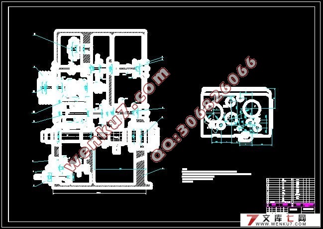
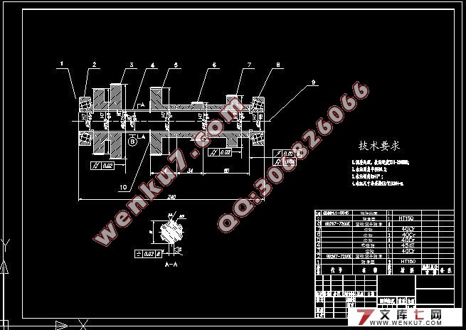
CA6140机床主轴箱的设计(开题报告,外文翻译,毕业论文说明书12000字,CAD图纸5张)
摘 要
作为主要的车削加工机床,CA6140机床广泛的应用于机械加工行业中,本设计主要针对CA6140机床的主轴箱进行设计,设计的内容主要有机床主要参数的确定,传动方案和传动系统图的拟定,对主要零件 进行了计算和验算,利用三维画图软件进行了零件的设计和处理, CA6140车床作为主要的车削加工机床,已广泛的应用于机械加工行业中。本文首先介绍了金属切削机床在国内外的研究状况,以及国内外发展差距。然后系统的介绍了CA6140主轴箱的组成及各个组成部分的功用。最后详细的阐述了本论文的研究内容,思路、主要方法及进度。
关键词 金属切削机床 CA6140 主轴箱。
Abstract
As a major turning processing machine, CA6140 machine widely used in mechanical processing industry, the design of the machine tool for CA6140 main spindle box design, design is the main content of machine tool of the main parameters of the sure, transmission scheme and transmission system graph of the recommended, the main parts are calculated and checked and the use of 3 d drawing software parts design and processing, CA6140 lathe as a major turning processing machine tool, have been widely used in mechanical processing industry in this paper first introduced the metal cutting machine tools in the domestic and foreign research condition, and the domestic and foreign development gap and then systematically introduces the CA6140 spindle box and composition of the function of each component of the last detail the research content of this paper, the main methods and ideas progress。
Key words: Metal cutting machine tools CA6140 spindle box
主要技术参数
工件最大回转直径:
在床面上 400毫米。
在床鞍上 210毫米。
工件最大长度(四种规格) 750、1000、1500、2000毫米
主轴孔径 48毫米
主轴前端孔锥度 400毫米
主轴转速范围:
正传(24级) 10~1400转/分
反传(12级) 14~1580转/分
加工螺纹范围:
公制(44种) 1~192毫米
英制(20种) 2~24牙/英寸
模数(39种) 0.25~48毫米
径节(37种) 1~96径节
进给量范围:
细化 0.028~0.054毫米/转
纵向(64种) 0.08~1.59 毫米/转
加大 1.71~6.33 毫米/转
细化 0.014~0.027毫米/转
横向(64种)正常 0.04~0.79 毫米/转
加大 0.86~3.16 毫米/转
刀架快速移动速度:
纵向 4米/分
横向 4米/分
主电机:
功率 7.5千瓦
转速 1450转/分
快速电机:
功率 370瓦
转速 2600转/分
冷却泵:
功率 90瓦
流量 25升/分
工件最大长度为1000毫米的机床:
外形尺寸(长×宽×高) 2668×1000×1190毫米
重量约 2000公斤


目录
前 言 1
1 机床的规格和用途 2
2 主要技术参数 3
3 传动方案和传动系统图的拟定 5
4 主要设计零件的计算和验算 8
4.2 传动系统的I轴及轴上零件设计 11
4.2.1 普通V带传动的计算 11
4.2.2多片式摩擦离合器的计算 13
4.2.3 齿轮的验算 15
4.2.4 传动轴的验算 18
4.3 传动系统的Ⅱ轴及轴上零件设计 21
4.3.1齿轮的验算 21
4.3.2传动轴的验算 25
4.3.3 轴组件的刚度验算 27
4.4 传动系统的Ⅲ轴及轴上零件设计 29
4.4.1 齿轮的验算 29
4.4.2 传动轴的验算 33
4.4传动系统的Ⅳ轴及轴上零件设计 37
4.4.1齿轮的验算 37
4.4.2传动轴的验算 41
4.5 传动系统的Ⅴ轴及轴上零件设计 46
4.5.1齿轮的验算 46
4.5.2传动轴的验算 51
4.5.3 轴组件的刚度验算 53
5 结论 56
6 致 谢 57
7 参考文献 57
|


