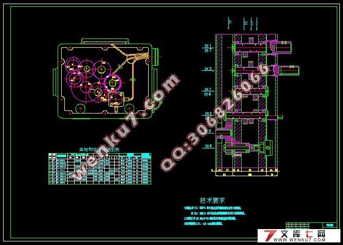
卧式双面组合镗床及工装设计(含工艺过程卡)(任务书,开题报告,外文翻译,毕业论文说明书20000字,进度检查表,CAD图纸4张)
摘 要
该篇论文为镗主轴箱的6个轴孔的变速箱组合镗床设计。镗床是主要用镗刀对工件已有的预制孔进行镗削的机床。通常以镗刀旋转为主运动,镗刀或工件的移动为进给运动。它主要是用于加工高精度孔或一次定位完成多个孔的精加工,此外还可以从事与孔精加工有关的其他加工面的加工。使用不同的刀具和附件还可进行钻削、铣削、切削,其加工精度和表面质量要高于钻床。镗床是大型箱体零件加工的主要设备,也可加工螺纹及外圆和端面等。
以箱体零件同轴孔系为代表的长孔镗削,是金属切削加工中最重要的内容之一。尽管现在仍有采用镗模、导套、台式铣镗床后立柱支承长镗杆或人工找正工件回转180°等方法实施长孔镗削的实例,但近些年来,一方面由于数控铣镗床和加工中心的大量使用,使各类卧式铣镗床的坐标定位精度和工作台回转分度精度有了较大提高。从机床结构上使工作台回转180°自定位的调头镗孔,几乎是成为了在该种机床上镗削长孔的唯一方法。
本设计说明书主要包括了组合机床总体设计过程,对工艺方案设计、总体设计、部件设计等几方面加以论述。
内容有产品工序分析,组合机床总体布置以及镗床主轴图的绘制。
关键词:主轴箱;组合镗床;加工工艺
Abstract
Gearbox combination boring lathe design this paper into 6 hole boring spindle box. Boring machine is mainly used for boring prefabricated holes on the workpiece has been the boring machine. Usually, boring cutter rotating main movement, the workpiece moving boring or for feed motion. It is mainly used for finishing machining high precision hole or a location to complete a plurality of holes, in addition to engage with the hole machining processing and other related processing surface.Different tools and accessories used can also be drilling, milling, cutting,, the machining precision and surface quality than that of drilling machine. Boring machine is the main equipment of large body parts processing. Can also be processed the thread and the outer circle and end.
Long hole boring to box part coaxial holes as the representative of the cut, is one of the most important content in the metal cutting. Although there are still using boring mode, guide sleeve, desktop milling and boring machine after the columns support the long boring bar or artificial alignment workpiece rotation of 180 DEG, examples of long hole boring. But in recent years, on the one hand because of the extensive use of CNC milling machine and machining center, precision of the coordinate positioning rotary precision and working table of horizontal boring and milling machine has been greatly improved. From the machine tool structure enable the rotary table 180 ° from the positioning of the turn-around boring, become almost the only method in the machine tool on the long hole boring.
This design instruction booklet mainly includes overall design process of machine tool, and discusses the aspects of design, process scheme for the overall design, component design.
The contents of product process analysis, combination of general layout of machine tool and boring spindle diagram.
Key words: spindle box; combination machine; processing technology
2 组合机床总体设计
组合机床的设计,目前基本上有两种情况[2]:
第一,是根据具体加工对象的具体情况进行专门的设计,这是当前最普遍的做法。
第二,是随着组合机床在我国机械行业的广泛使用,广大工人总结自己生产和使用组合机床的经验,发现组合机床不仅在其组成部件方面有共性,可设计成通用部件,而且一些行业在完成一定工业范围的组合机床是具有很大相似度的,有可能设计为通用的组合机床,这种机床被称为“专能组合机床”。这种专能组合机床不需要每次按具体加工对象进行专门的设计和生产,可以设计为通用配件,组织成批生产,然后按被加工零件的具体需要,配以简单的夹具及刀具,即可组成加工一定要求对象的高效设备。
2.1 零件图分析
对零件图进行分析可以熟悉产品的性能及用途、工作条件等,从而成为各项技术要求制定的依据,找出主要的技术要求和关键技术问题。
这次设计要加工的零件是变速箱箱体。
2.1.1 零件的结构特点及功用
变速箱是汽车、拖拉机等传动系统的主要部件,而变速箱箱体是变速箱的主要零件,它的主要作用是支承各种传动轴,是典型的箱体类零件。
如图所示为汽车变速箱体零件图,前端面上Φ110H7/Φ100H7 同轴孔为 输入、输出轴轴孔,Ф62/Ф90 同轴孔为中间轴轴孔,后端面上Φ30孔为倒挡齿轮轴轴孔。
研究内容
在规定时间内完成下列任务要求:
1.设计技术要求:分析被加工零件的形状和主要轮廓尺寸以及本工序机床设计有关部位结构形状和尺寸;本工序所选的定位基准、压紧部位及加紧方向;本工序加工表面的尺寸、精度、表面粗糙度、形位公差等技术要求以及对上道工序的技术要求并拟定机械加工工艺路线、进行工艺规程设计、设计一套适用该变速箱加工的卧式双面组合镗床。
2.设计工作量要求:
1)抄画零件图;
2)编制机加工工艺文件;
3)绘制卧式双面组合镗床装配图及全套非标准零件图;
4)编写设计说明书(30页);
5)翻译8000以上外文印刷字符或译出4000汉字以上的有关技术资料或专业文献。


目 录
摘 要 III
ABSTRACT IV
目录 V
1 绪论 1
1.1 组合机床及其特点 1
1.2 组合机床的组成和分类 2
1.3通用部件的分类及简介 2
1.4 组合机床的工艺范围及发展方向 3
2 组合机床总体设计 5
2.1 零件图分析 5
2.1.1 零件的结构特点及功用 5
2.1.2 变速箱的主要技术要求 6
2.1.3 变速箱的体的材料和毛坯 6
2.2 组合机床工艺方案的制定 6
2.2.1 工艺基面的分析 7
2.2.2 加工工艺的分析 7
2.2.3加工余量的确定 8
2.2.4 确定加工工艺方案应注意的问题 8
2.2.5 制定工件加工工艺路线 9
2.2.6 组合机床切削用量的选择 10
2.3 组合机床总体设计 11
2.3.1 被加工零件工序图 11
2.3.2 加工示意图 12
2.3.3 动力部件的选择 15
2.3.4 机床联系尺寸图的绘制 18
2.4 多轴箱的传动系统设计 20
2.5 箱体补充加工图 22
2.6本章小结 23
3 装置的确定 24
3.1导向装置的作用、类型及结构形式 24
3.2 定主轴的类型及镗杆的确定 25
3.3 本章小结 26
4 组合机床生产率的计算 27
4.1 机床生产率的计算 27
4.2 编写组合机床生产率计算卡 28
4.3 本章小结 29
5 结论与展望 30
5.1 结论 30
5.2 展望 30
致 谢 31
参考文献 32
|


