主架体单工位镗孔组合机床总体设计(含CAD图)
来源:wenku7.com 资料编号:WK717959 资料等级:★★★★★ %E8%B5%84%E6%96%99%E7%BC%96%E5%8F%B7%EF%BC%9AWK717959
以下是资料介绍,如需要完整的请充值下载。
1.无需注册登录,支付后按照提示操作即可获取该资料.
2.资料以网页介绍的为准,下载后不会有水印.资料仅供学习参考之用. 密 保 惠 帮助
资料介绍
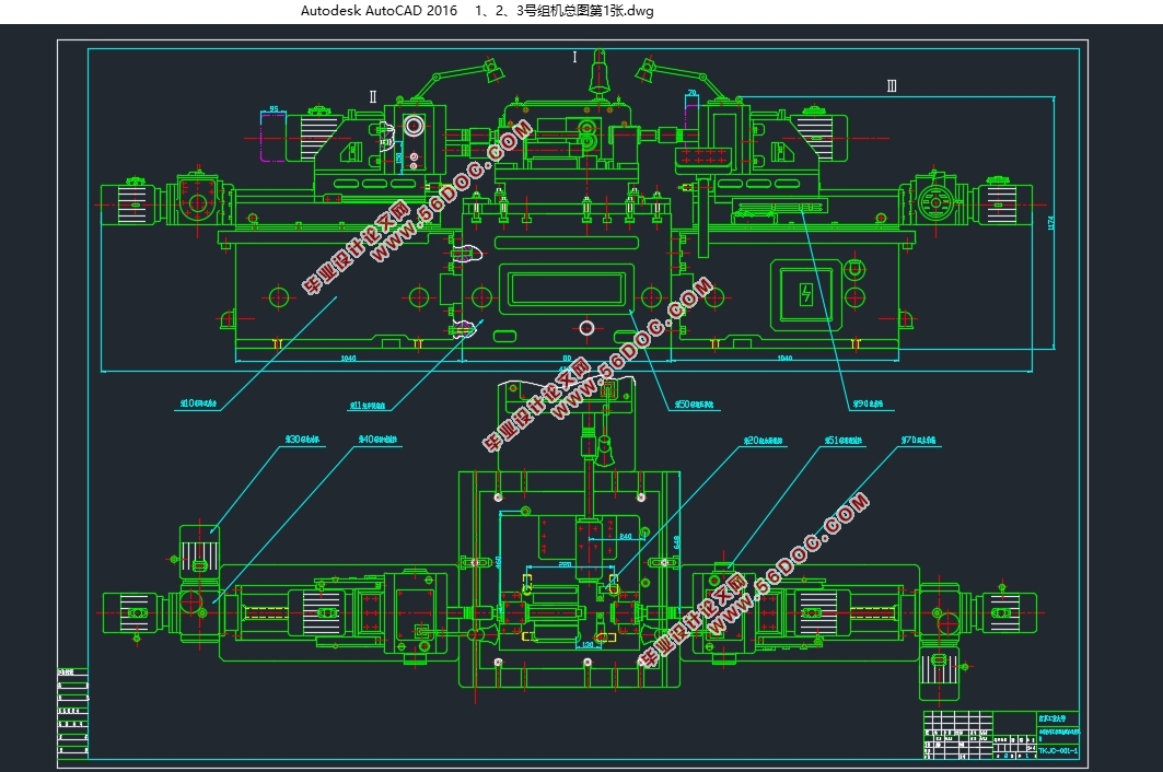
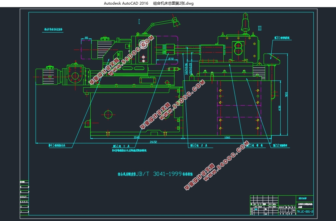
主架体单工位镗孔组合机床总体设计(含CAD图)(论文说明书12000字,CAD图4张)
摘 要
本文对主架体单工位镗孔组合机床的加工工艺进行了详细的分析,就其孔的加工提出了“单工位加工,达到产品图样的精度要求”的思路。根据这一思路设计了主架体单工位镗孔组合机床。本文设计了主架体单工位镗孔组合机床的加工方案,并就选择的单工位加工方案作了详细说明,最终完成了主架体单工位镗孔组合机床的总体设计。
关键词 主架体单工位镗孔组合机床
ABSTRACT
In this paper, the main frame body simplex bit boring modular machine tool processing technology to carry on the detailed analysis, with respect to its hole processing is put forward the "simplex bit processing, to fulfill the requirements of the accuracy of product design". According to this train of thought to design the main frame body simplex bit boring modular machine tool. This paper designed the main frame body simplex bit boring.
Key words The frame body simplex bit boring modular machine tool


目录
摘 要 I
ABSTRACT II
第一章 绪论 2
1.1组合机床的现状 2
1.2的设计步骤 3
1.2.1研究 3
1.2.2工艺方案的拟订 3
第二章 方案论证 9
2.1方案Ⅰ(多工序加工) 9
2.2方案Ⅱ(多工位加工) 10
2.3方案Ⅲ(单工位加工) 10
第三章 主架体单工位镗孔组合机床总体设计 11
3.1配置形式的选择 11
3.1.1依据 11
3.1.2形式选择 11
3.2主架体镗孔加工工序图 11
3.3主架体镗孔加工示意图 13
3.3.1刀具选择 14
3.3.2浮动卡头选择 14
3.3.3导向机构及主要参数的确定 15
3.3.4模具的选择 15
3.3.5动力头的工作循环及行程确定 16
3.3.6切削用量的确定 19
3.4主架体单工位镗孔组合机床联系尺寸总图 20
3.4.1动力部件的选择 20
3.4.2主轴箱确定 21
3.4.3中间底座的确定 22
3.5主架体镗孔组合机床生产率计算卡 23
3.5.1理想生产率 23
3.5.2 实际生产率 24
3.5.3机床负荷率 24
3.5.4 生产率计算卡 25
结论 27
参考文献 28
致谢 29
|


