JHMB-28慢速绞车设计(含CAD图)(论文说明书14000字,外文翻译,CAD图6张)
摘要
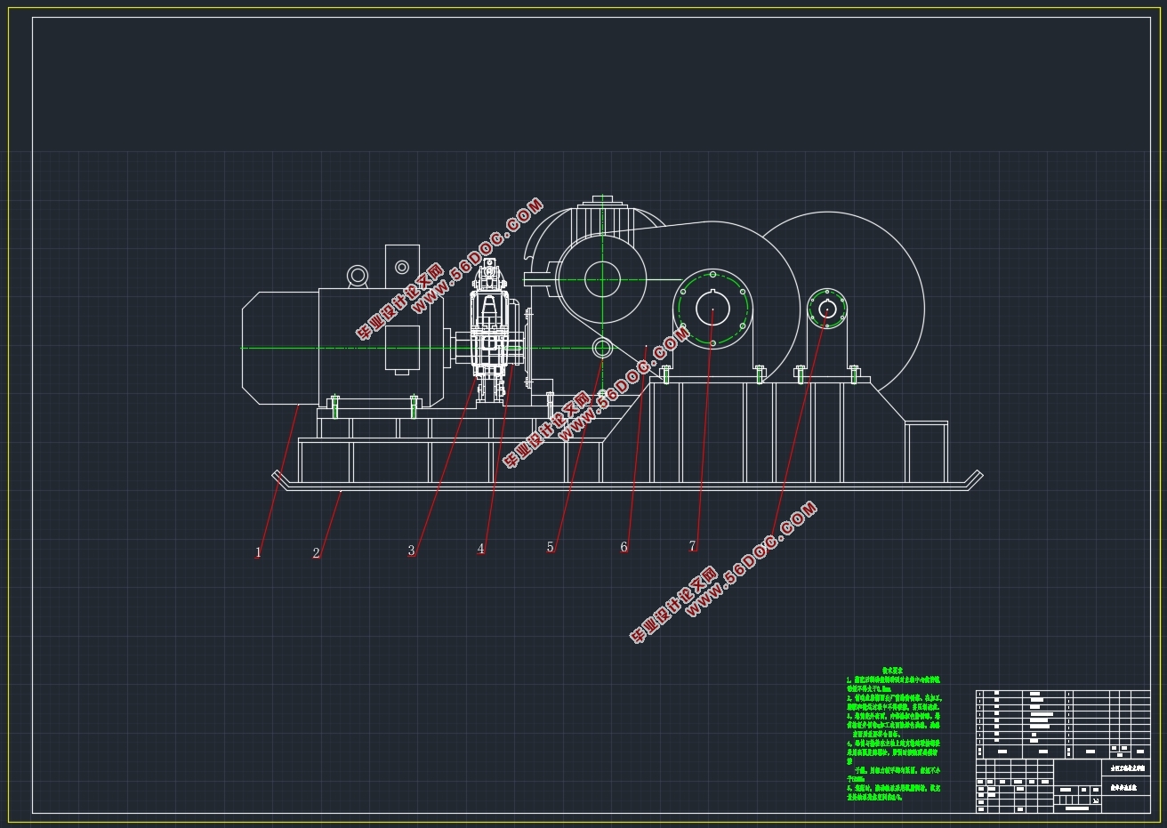
JHMB-28型慢速绞车是一种典型的矿山辅助搬运设备。该型绞车主要适用于煤矿井下有煤尘或爆炸性气体环境中在倾角小于30°的巷道牵引重物以及采煤工作面液压支架的撤移、调向和搬运之用。
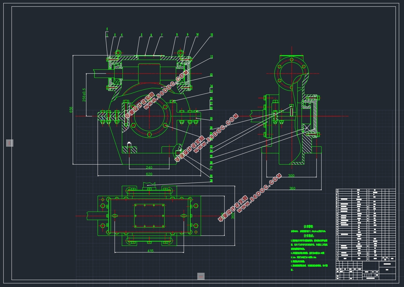
本次设计的绞车主要采用齿轮-蜗杆传动系统传动,包括圆柱直齿轮传动和圆弧蜗轮蜗杆传动。蜗杆用轴向剖面为圆弧形的砂轮进行精加工,可获得较高的精度,具有承载能力大,传动效率高的优点,被广泛用于冶金、矿山、化工、建筑、起重等机械设备中。
该绞车结构紧凑,外形尺寸小;结构为近似布置,外形美观,成长条形,底座呈雪橇状,实现了可移动性,运转平稳,安全可靠,操作方便。
绞车又称为卷扬机,主要运用于建筑、水利工程、林业、矿山、码头等的物料升降或平拖,是用卷筒缠绕钢丝绳或链条以提升或牵引重物的轻小型起重设备。
本次设计的思路是先以给定的数据确定钢丝绳的直径参数,而后计算卷起钢丝绳的卷筒的各个尺寸参数,通过给定的数据推出电动机的转速和功率,从而选择电动机,确定传动比,再分配给各个减速器计算其各个参数,最后计算及校核各轴、联轴器、制动器等机构零件。
本文主要阐述了慢速绞车的发展和对慢速绞车的具体设计以及零部件的选用过程,本次设计中把两级齿轮分别装在电动机和卷筒的两侧,使结构紧凑,外形尺寸小,减少底座材料的使用降低了成本;成长条形,底座呈雪橇状,实现了可移动性,运转平稳,安全可靠,操作方便。由于该机器用于矿场上,所以必须具有一定的防爆能力,故而选用防爆电动机代替原来的鼠笼式电动机。
关键词:慢速绞车;圆弧蜗轮蜗杆;结构紧凑;可移动
DESIGN OF JHMB-28 LOW-SPEED WINCH
Abstract
The JHMB-28 slow winch is a typical mine auxiliary handling equipment. This type of winch is mainly suitable for the removal, adjustment and handling of roadway traction weights with an inclination of less than 30 ° and hydraulic support for coal mining face in coal mine underground environment with coal dust or explosive gas.
The winch mainly adopts gear-worm transmission system, including cylindrical straight gear transmission and circular worm gear transmission. Worm with axial profile of Arc wheel for precision processing, can obtain higher accuracy, has a large carrying capacity, the advantages of high transmission efficiency, is widely used in metallurgy, mining, chemical, construction, lifting and other mechanical equipment.
The winch has compact structure and small shape. The structure is approximately arranged, the appearance is beautiful, the shape is long, and the base is sleigh, which realizes mobility, smooth operation, safe and reliable, and convenient operation.The winch, also known as a hoist, is mainly used in the lifting or towing of materials such as buildings, water Conservancy projects, forestry, mines, and docks. It is a light and small lifting device that uses a coil to twine wire ropes or chains to lift or pull heavy weights.
The idea of this design is to first determine the diameter parameters of the wire rope with the given data, and then calculate the dimensions of the reel of the rolled wire rope, and use the given data to derive the speed and power of the motor, thus selecting the motor. Determine the transmission ratio, Reassigned to each speed reducer to calculate its various parameters, and finally calculate and check each shaft, coupling, brake and other institutional parts.
This paper mainly describes the development of slow winch, the design of slow winch and the selection process of parts. In this design, the two gears are installed on the sides of the motor and reel respectively, so that the structure is compact and the shape is small. The reduction in the use of base materials reduces the cost; In the shape of a long strip, the base is sledge-shaped, which realizes mobility, smooth operation, safe and reliable, and easy to operate. Since the machine is used in the mine, it must have a certain explosion-proof capability. Therefore, the explosion-proof motor is used instead of the original rat cage motor. The winch mainly adopts gear-worm transmission system transmission, including cylindrical straight gear transmission and circular worm worm transmission. Worm with axial profile of Arc wheel for precision processing, can obtain higher accuracy, has a large carrying capacity, the advantages of high transmission efficiency, is widely used in metallurgy, mining, chemical, construction, lifting and other mechanical equipment.
Key words: slow winch; Round arc worm worm; Compact structure; movable
2.1 设计条件
1)机器用途:煤矿井下有煤尘或爆炸性气体环境中和其他矿山在倾角小于 30°的巷道牵引重物及回收支柱用的慢速绞车;
2)工作情况:工作稳定、平稳,间歇工作(工作与停歇时间比为1:2),绳筒转向定期变换;
3)运动要求:绞车绳筒转速误差不超过8%;
2.2 原始数据
型号 JHBM-28
钢丝绳外层最大静张力(kK) 280
钢丝绳平均静张力(kK) 320
钢丝绳平均绳速(m/s) 0.04 ~0.17
卷筒容绳量(m) 250
钢丝绳直径(mm) 30
钢丝绳结构 绳6×19
钢丝绳公称抗拉强度(MPa) 1670


目录
摘要 i
Abstract ii
1 绪论 1
1.1 引言 1
1.2 概述 2
1.2.1 慢速绞车结构的分析 2
1.2.2 电气设备 2
1.2.3 制动部分 2
1.3 减速器 3
1.4 中间轴装置 3
1.5 卷筒装置 3
1.6 底座 3
1.7 慢速绞车的布置方式 3
1.8 国内外绞车的概述 4
2 总体设计 7
2.1 设计条件 7
2.2 原始数据 7
2.3 传动方案的拟定 7
3 电动机的选择 9
3.1 电动机类型和结构型式 9
3.2 系统的总效率 9
3.3 电动机的功率 9
3.4 电动机的转速 10
4 卷筒的确定 11
4.1 卷筒的概述 11
4.1.1 卷筒的结构 11
4.1.2 卷筒的材料 11
4.2 卷筒尺寸的计算 11
5 减速器的选择 14
4.3 减速器的主要型式及其特征 14
4.4 减速器的分类 14
4.5 常见减速器的特点 14
4.6 减速器的选择 15
5 联轴器的选择 16
5.1 联轴器的概述及分类 16
5.2 联轴器的选择 16
7 制动器的选择 17
5.3 制动器的概述 17
5.4 制动器的分类 17
5.5 制动器的选用 17
6 中间轴装置的设计 19
6.1 中间轴上高速级齿轮的设计 19
6.2 中间轴上低速级齿轮的设计 22
6.3 轴的设计计算 25
6.4 轴的作用 25
6.4.1 轴的分类 25
6.4.2 轴的设计计算 26
7 系统传动部件的校核 27
7.1 中间轴上键的校核 27
7.2 中间轴上轴承的校核 28
结论 29
参考文献 30
外文资料 31
中文译文 36
致谢 39
|


