微型车桥壳零件生产线搬运机械手结构设计(含CAD装配图)(任务书,开题报告,论文说明书20000字,CAD图2张)
摘要
根据微车后桥桥壳零件生产线的总体布局,针对市面上现有搬运机械手存在的缺点与不足,并借鉴国内外最新研究成果,以桥壳零件的加工工序以及具体加工工位和加工要求为基础,设计出了一个专用机械手从而实现了桥壳零件在生产线上的装卸工作。
本文对机械手进行了总体方案设计,确定了机械手的坐标形式、自由度及相关技术参数。同时,设计了机械手的夹持式手部结构、腕部回转机构、小臂升降机构、大臂伸缩机构和机身回转机构,并完成了各机构所用驱动气缸的选型和计算。借用SolidWorks软件对机械手的整体结构及各个零部件进行了三维建模,并应用ANSYS Workbench软件对机械手关键零部件进行了静力学分析、强度分析和模态分析。设计出了机械手的工作流程和运动形式,并在软件中实现了机械手在工作状态下的运动仿真。
关键词:搬运机械手;结构设计;气缸选型;三维建模;有限元分析;运动仿真
Abstract
According to the overall layout of the mini-vehicle rear axle housing part production line, concerning the shortcomings and deficiencies of existing handling manipulators on the market, and drawing on the latest research results at home and abroad ,in this paper, a special manipulator is designed based on the machining process of the axle shell part and the specific processing station and processing requirements, so that the loading and unloading of axle housing parts on the production line is realized.
This article has carried on the overall plan design to the manipulator, and determined the manipulator's coordinate form, the degree of freedom and the related technical parameter. At the same time, the gripping type hand structure, wrist rotation mechanism, lift arm, telescopic arm and body rotation mechanism of the manipulator are designed, and the selection and calculation of the drive cylinder used by each mechanism are completed.Solidworks is used to perform three-dimensional modeling of the robot's overall structure and its components. ANSYS Workbench is used to perform static analysis, strength analysis and modal analysis on the key components of the manipulator. The workflow and movement forms of the manipulator are designed, and the manipulator's motion simulation under working condition is implemented in the software.
Key Words:handling manipulator;structural design;cylinder selection;3D modeling;finite element analysis;motion simulation
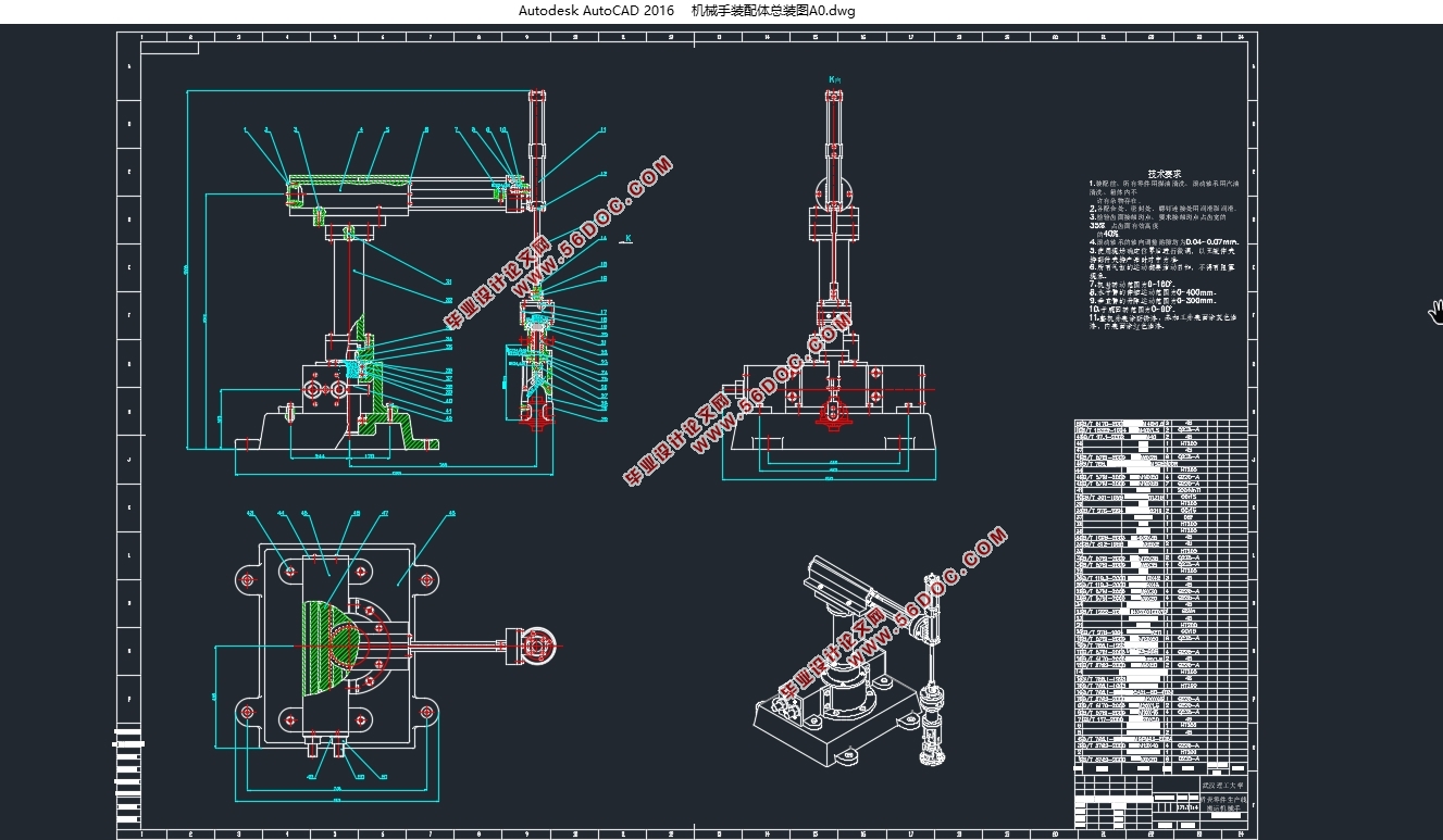
本课题设计的机械手主要由以下五部分组成:
(1)手部夹持部分,采用一个直线气缸,通过驱动活塞移动实现手爪的开闭。
(2)腕部回转部分,采用一个回转气缸实现手部90°回转。
(3)小臂升降部分,采用一个直线气缸来实现手臂在300mm内升降。
(4)大臂伸缩部分,采用一个直线气缸来实现手臂在400mm内伸缩。
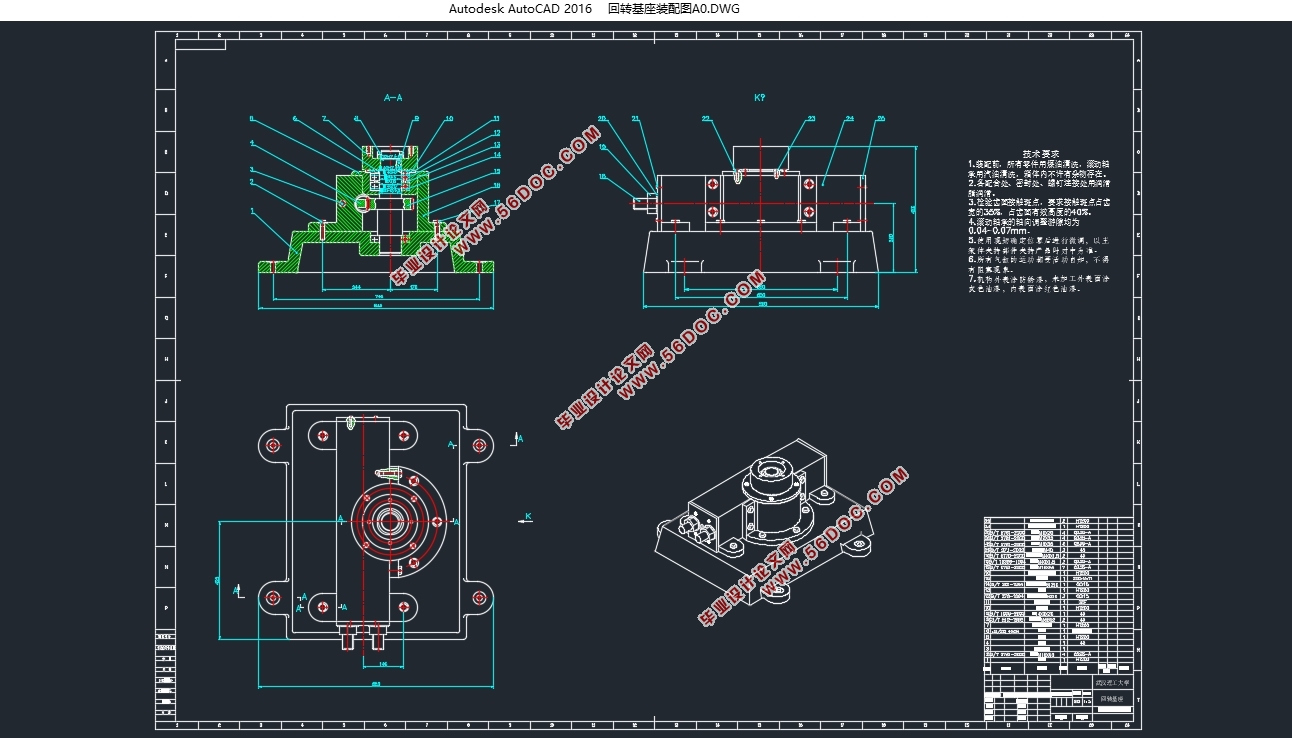
(5)机身回转部分,采用一个回转气缸来实现机械手在180°范围内回转。
为了研究的方便,参照机械手在工作状态下所具有的运动状态,作出机械手的运动示意图如图2-4-2所示。
根据图2-4-2可以看出本课题要设计的机械手的主要任务就是将待加工的桥壳零件毛坯从传送带搬运到加工生产线上,待加工完成后再将已加工的成品零件从加工生产线上卸装回传送带上。其工作流程:机械手原位→小臂上升→机身左转→大臂前伸→小臂下降→手爪闭合夹紧工件→小臂上升→大臂回收→机身右转→大臂前伸→小臂下降→手爪张开放置工件→小臂上升→大臂回收→回到原位停止或进行下一个循环。
2.5机械手的相关设计参数
根据课题给出的桥壳零件的相关尺寸参数,可以估算其重量在 之间,为了留有一定裕量,将其最大抓取重量设为40kg,送料精度设为 ,其余参数见表2-1。
表2-1 桥壳生产线搬运机械手设计参数表
部件名称 工作行程 运行速度
手部夹紧机构 0~70mm 50mm/s
腕部回转机构 0~90° 90°/s
小臂升降机构 0~300mm 300mm/s
大臂伸缩机构 0~400mm 400mm/s
机身回转机构 0~180° 90°/s


目录
摘要 I
ABSTRACT II
第1章绪论 1
1.1 课题背景及意义 1
1.2 机械手的组成和分类 2
1.2.1 机械手的组成 2
1.2.2 机械手的分类 3
1.3 机械手国内外发展现状 4
1.4 机械手发展前景及方向 5
第2章机械手总体方案设计 6
2.1 机械手的生产线布局 6
2.2 机械手的坐标形式与自由度 7
2.3 驱动机构的选择 8
2.4 机械手的整体结构及工作流程 8
2.5机械手的相关设计参数 9
第3章机械手传动部件的结构设计 10
3.1 手部夹紧机构的设计 10
3.2 腕部回转机构的设计 12
3.3 小臂升降机构的设计 12
3.4大臂伸缩机构的设计 15
3.5机身回转机构的设计 16
3.6本章小结 17
第4章动力部件的计算与选型 18
4.1 手部夹紧气缸的计算 18
4.1.1 手部结构的应力分析 18
4.1.2 夹紧力的计算 19
4.1.3 驱动力的计算 19
4.1.4 气缸内径的选择 20
4.2 腕部回转气缸的计算 22
4.2.1 腕部回转力矩的计算 22
4.2.2 回转气缸内径的计算 25
4.2.3 腕部回转气缸的选型 26
4.3 臂部伸缩气缸的计算 27
4.3.1 驱动力的计算 27
4.3.2 缸径及活塞杆的选择 29
4.3.3 缸筒壁厚的设计计算 30
4.3.4 伸缩气缸的选型 31
4.4 机身回转气缸的计算及选型 32
4.5 本章小结 34
第5章基于ANSYS WORKBENCH的机械手有限元分析 35
5.1腕部结构分析 35
5.2立柱结构分析 36
5.3机械手模态分析 39
5.4本章小结 42
第6章机械手运动设计 43
6.1机械手的工作流程 43
6.2基于SOLIDWORKS的机械手运动仿真 45
6.3本章小结 48
第7章总结与展望 49
参考文献 50
致谢 52
|


