具有4-20MA远传信号的液位计设计(含CAD零件装配图,UG三维图)(任务书,开题报告,外文翻译,论文说明书12000字,CAD图31张,UG三维图)
摘要:在现代制造业中,油位计在各种非标准自动化设备中的应用极为广泛,基本上安装在封闭的油箱上用来测量油液位的液位高度值,其通过内部结构将液位高度的实时变化值传动至外置指针表盘,以供使用者观测。传统的油液位测量仪在设计中难免存在不足之处,比如结构较为复杂且实现的功能很少,尤其不能进行实时信号的远距离传输,精度方面更是达不到应有的要求。本论文所设计的油液位测量仪,充分考虑了我国现阶段机械行业普遍制造工艺现状及代加工工厂的实际设备情况,为此设计了一套具有远传信号的YZF型油液位测量仪,在满足传统油液位测量仪的基础上,增添了新的功能,尤其在结构方面,进行了大幅度优化,更好地安排内置零件的空间分布位置,并且尽最大可能满足制造精度要求,以实现更高精度的远传信号。
论文采用依靠计算机辅助设计软件UG及Auto-CAD进行三维设计和二维工程图绘制,在UG软件按照自顶向下的设计理念进行结构设计的方法,在设计的整个过程中,通过在满足加工工艺要求的同时,也在零件的特殊位置施加曲面设计以更好地满足人的视觉需要,当然考虑了研发制造成本,在零件材料的选取上,尽可能在材料满足耐磨耐腐蚀的基础上选择较便宜的材质。同时对于齿轮的传动精度方面,在工程图中有所注明,即加工要求较高的手段,得出了所设计的油液位测量计能满足弥补市面上现存产品的不足之处,取长补短以更好的适应设备得的实际需求的结果和重要的结论。
关键词:液位计;UG;Auto-CAD
Design of liquid level meter with 4-20mA remote signal
Abstract: In modern manufacturing, the oil level meter is widely used in all kinds of non-standard automation equipment. It is basically installed in closed oil tank to measure the level of liquid level of oil level. It drives the real time change value of the level height to the external pointer dial through the internal structure for the user to observe. The traditional oil level measuring instrument is difficult to avoid in the design, such as the complex structure and few functions, especially the long distance transmission of real time signal. The oil level measuring instrument designed in this paper fully considers the current situation of the general manufacturing process in our machinery industry and the actual equipment of the processing plant in our country. A set of YZF type oil level measuring instrument with long transmission signal is designed, which has added new functions, especially on the basis of the traditional oil level measuring instrument. In the aspect of structure, a large scale optimization is carried out to better arrange the spatial distribution of the built-in parts, and to meet the requirements of the manufacturing precision as much as possible to achieve a higher precision remote transmission signal.
The paper adopts the computer aided design software UG and Auto-CAD for three-dimensional design and drawing of two-dimensional engineering drawings. In the UG software, the design method of the structure is carried out according to the top-down design idea. In the whole process of the design, the surface design is applied to the special position of the parts by meeting the requirements of the processing technology. for the transmission precision of gear, it is indicated in the engineering drawing, that is, the means of higher processing requirements, and the designed oil level measuring meter can meet the shortcomings of the existing products on the market and make up for better the results and important conclusions of the actual needs of the equipment.
Keywords:Liquid level meter;UG;Auto-CAD
油位计的工作原理
油位计设计所用的材质比较重要,毕竟它的末端小球及相应的元器件需要长时间浸泡在油液中,其需要具有耐腐蚀、耐高温、耐冲击和寿命长等特性。因此考虑的材质有用于高温高压环境下的SUS304不锈钢、SUS316不锈钢,高强度及耐腐蚀性的塑料材质PP或PVC等[4]。
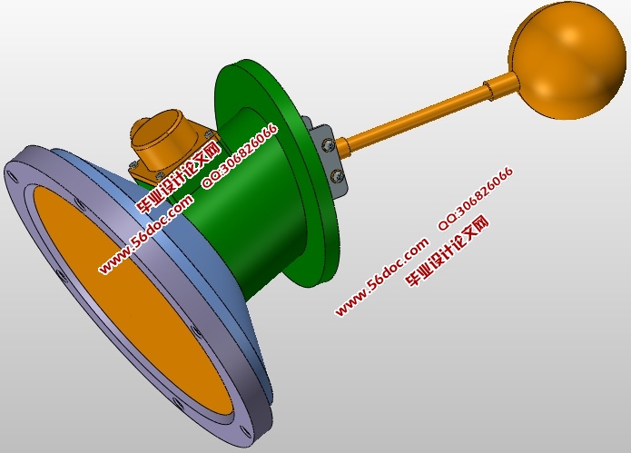
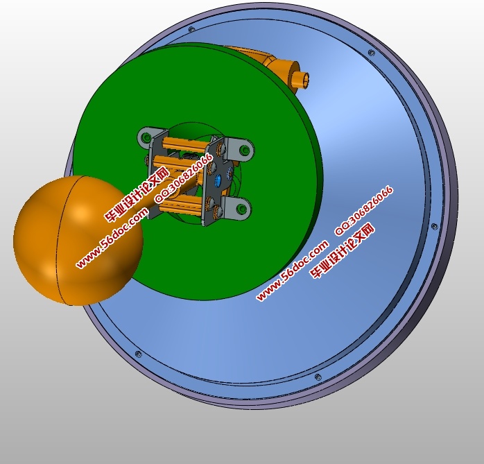
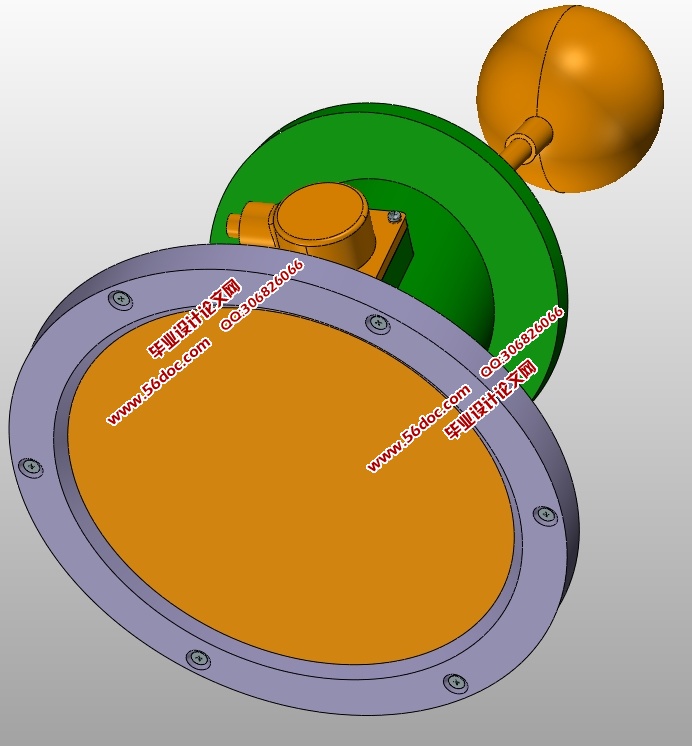
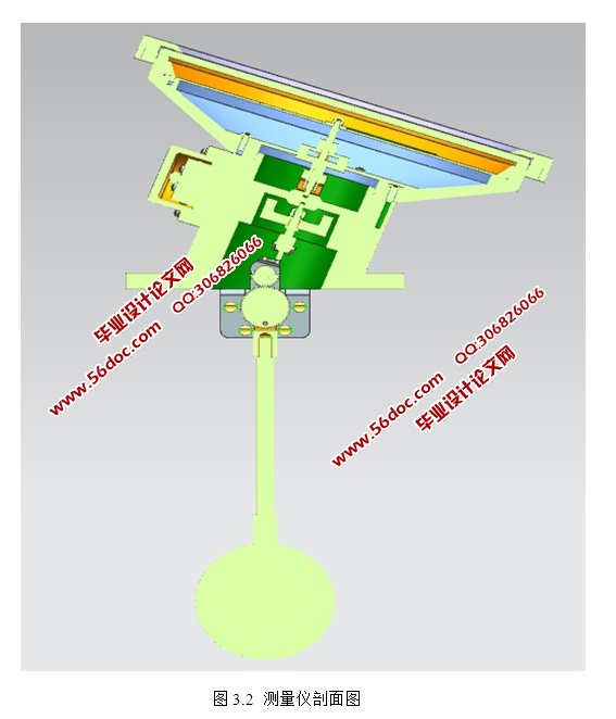
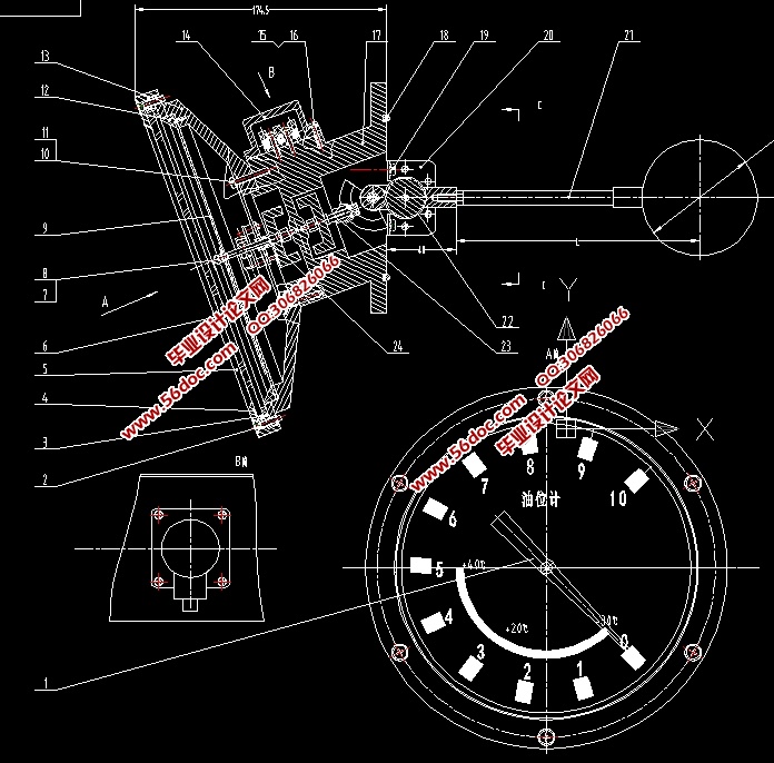
如图2.3所示本论文所设计的油液位测量计的工作原理是,仪器末端有一漂浮的质量很轻的小球,此小球的作用是随着油液位的高度变化而对应上浮下沉,通常是将其放置在密闭的防腐蚀橡胶管或金属管内,小球设置有由环形扣件紧固的多个干簧管,连杆贯穿干簧管使小球固定连接着连杆。这样一来小球的上下浮动就能驱动连杆动作。这样设计的原理是市面上油液位计的普遍设计方法。这样设计的好处是,能实现小球与液面的接触面积尽可能多,实现多点控制测量,因干簧管的寿命比较长且不用单独供电,一般是350万次使用寿命。另外YZF型油液位计的制造研发成本相对较低,有很好的市场应用前景,其电气走线也比较简单,控制系统也好设置。
目 录
摘要 I
ABSTRACT Ⅱ
1 绪论 1
1.1 课题研究的目的及意义 1
1.2 国内外研究现状 3
1.3 本课题研究内容 3
2 油位计的分析 5
2.1 油位计的构成 5
2.2 油位计的工作原理 6
2.3 影响油位计精度的因素 7
2.4 油位计的应用 8
3 油位计的设计 11
3.1 油位计的工艺设计 12
3.2 表盘与表体 13
3.3 浮球的设计 14
3.4 传动部分的设计 14
3.5 信号传输电路与报警电路的设计 16
4 油位计参数的计算 19
4.1 油位计外轮廓参数的计算 19
4.1.1 表盘的直径和量程 19
4.1.2 表体设计 19
4.2 设计摆杆 20
4.2.1 摆杆与浮球、指针之间的运动形式 20
4.2.2 摆杆的摆动角度及长度 21
4.3 齿轮的计算与选择 21
4.3.1 齿轮种类的选择 22
4.3.2 齿轮参数的确定 22
4.3.3 齿轮设计校核 24
5 硬件电路设计 27
5.1 具有远传信号的电路设计 27
5.2 报警电路设计 27
6 总结 29
参考文献 30
致 谢 31
附录A 33
外文文献及翻译 33
|


