人工关节仿生试验机的设计(含CAD零件装配图)
来源:wenku7.com 资料编号:WK717286 资料等级:★★★★★ %E8%B5%84%E6%96%99%E7%BC%96%E5%8F%B7%EF%BC%9AWK717286
以下是资料介绍,如需要完整的请充值下载。
1.无需注册登录,支付后按照提示操作即可获取该资料.
2.资料以网页介绍的为准,下载后不会有水印.资料仅供学习参考之用. 密 保 惠 帮助
资料介绍
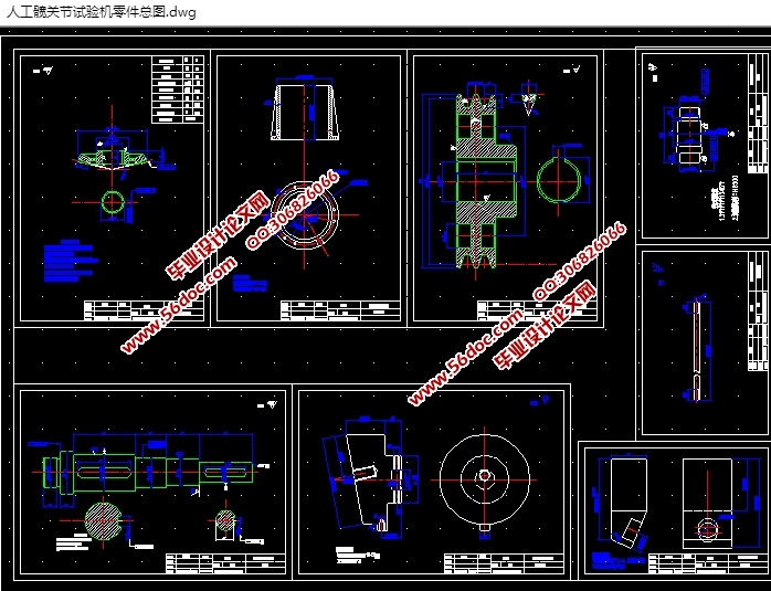
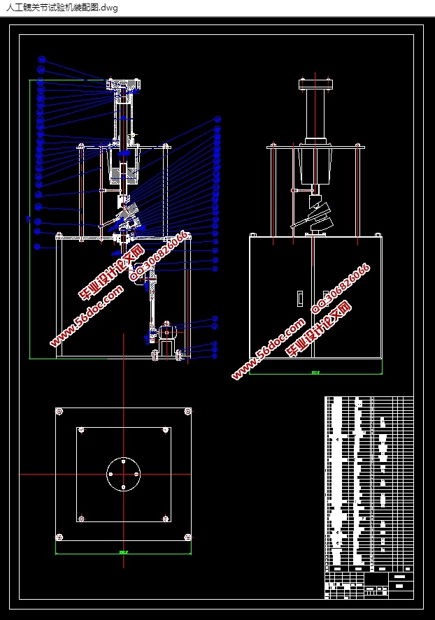
人工关节仿生试验机的设计(含CAD零件装配图)(论文说明书15700字,CAD图纸9张)
DESIGN OF BIONIC TESTING MACHINE FOR ARTIFICIAL JOINTS
摘要
本课题是对人体髋关节模拟试验机机械传动部分的研制。在上个世纪,就有许多国家已经研究出很多种的关节仿生试验机的设备,并且发展至今,全球已经有几千万人通过置换仿生关节,重新可以正常行走。这个实验机的工作原理是将股骨头和髋臼部件试样按照人体正常位置安装于试验台上,通过试验装置使两者之间产生相对运动。该试验机设计时考虑的主要因素是使其在实验室环境中能够正确模拟人体髋关节的实际运动状况,以此来使试件在试验过程中产生的摩擦机理、磨损形式与实际使用条件下相一致,从而可以准确、可靠地测试人工关节材料的生物摩擦学特性参数,这些参数可以为临床应用提供指导性试验数据。
关键词:仿生试验机;人的髋关节;摩擦性能
Abstract
This topic is the development of the mechanical transmission part of the human hip joint simulator. In the last century, many countries have studied many kinds of equipment for the bionic test machine of joint. And so far, tens of millions of people in the world have been able to walk normally through replacement of bionic joints in the world. The principle of this experiment machine is to install the specimen of the femoral and acetabular parts on the test bed in the normal position of the body, and make the relative motion between the two. The main factor to be considered in the design of the test machine is that it can correctly simulate the actual movement of the human hip joint in the laboratory environment so that the friction mechanism and wear form produced in the test process are in accordance with the actual conditions, thus the birth of the artificial joint material can be accurately and reliably tested. The tribological properties of these parameters can provide guidance test data for clinical application.
Keywords bionic testing machine human hip joint tribological properties


目 录
摘要 I
Abstract II
1绪论 1
1.1 仿制髋关节试验设备的背景 1
1.2人工关节仿生试验机到现在为止的研究情况 2
1.3 这次设计的主要目的 4
2设计方案的选择 5
2.1 人体髋关节的组成和运动特点 5
2.1.1 髋关节结构的运动 6
2.1.2 人工仿制的髋关节组成 6
2.2 设计的方案的提出与选择 7
2.3 方案中各机构的运动特性分析 10
3 试验机的选用设计计算 12
3.1选择电动机的类型 12
3.2带传动的设计 12
3.3选择减速器的类型 15
3.4 锥齿轮的设计 16
3.4.1 锥齿轮的主要几何尺寸设计计算 16
3.5 设计主传动轴的结构 22
3.5.1 选取轴的材料 22
3.5.2 选取轴的毛柸 22
3.5.3 确定主轴的最小直径 23
3.5.4 设计轴上的结构构成 23
3.6 设计摆轴的结构 28
3.6.1摆轴的材料的选择 28
3.6.2摆轴的最小直径的选择计算 28
3.6.3摆轴上装配的设计 28
3.6.4 进行摆轴的强度校核,运用弯扭合成校核 29
3.6.5摆轴上圆锥滚子轴承的校核计算 30
3.7 试验机的密封设计 31
结论 34
致谢 35
参考文献 36
|


