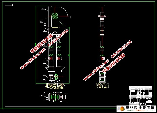
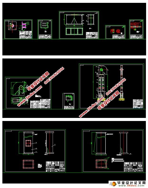
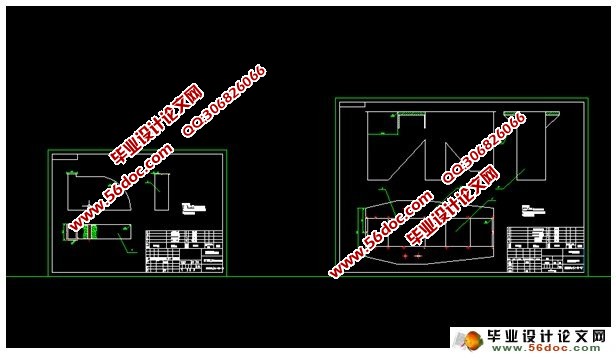
斗式提升机机头及中间节设计(含CAD零件图和装配图)(任务书,论文说明书6200字,CAD图12张,答辩PPT)
摘 要
关键词:1、TDTG50/24斗提机由机头、机座、机筒、观验机筒、减压机筒、畚斗、畚斗胶带、传动装置等部分组成。
2、机头部件由机头座、机头盖、头轮、头轮轴、轴承座、密封盖等部分组成,机头座上设有检修窗及调整挡板。
3、 中间节有三部分组成(1)观验检修机筒(2)普通机筒(3)减压机筒
(1)观验检修机筒
观验检修机筒设有检修门,可以供观验和检修之用,机筒由优质钢板折弯咬边联结,美观,强度好,密封性能佳,上下端焊接法兰,用于连接其他部件
(2)普通机筒 普通机筒没有检修门,其结构和观验机筒一样
(3)减压机筒 减压机筒可以使物料空气循环,机筒内压力平衡,空气流通更顺畅。
4、传动装置一般采用摆线针轮减速电动机通过皮带传动(或者联轴器、及链轮传动)带动头轮轴传动,也可采用普通电动机通过皮带传动带动悬挂式轴装减速器,其减速器是套装在头轮轴的伸出端上。以上两种传动方式其电机(或减速电机)均应安装在电机架上,当斗提机设计高度小于10米时也可以安装在机座上。
Abstract
The lifting machine is one of the large-scale regular machine,used in the rise or fall and transport of various kinds of heavy objects. The small-scale lifting machine plays an important role too in daily life. TDTG50/24 lifting machine is made up of the head ,the middle one and motor,decelerator.It links by the shafts.The motor is the power source,the decelerator is a transmission,the cylinder,in order to carry out and control some,among then,the design of each part
The head one is made up by the basic segment , the hat ,the pulley ,the head shaft,and the bearing .There are some parts in order to check the lifting machine .
The middle parts are used to check the machine.There are three segments,including the cylinder.one,the checking one,and the common one .
The cylinder one is made up by the window,which is used to watch and check the lifting machine.It looks very nice,and the force is enough.
The common one dose not have the check one,and it looks like the above one .The part which lets down the press.It can make the air as a cycle .
The motor usually takes a decelerator..(the flexible coupling and the transport).It works by the shaft or by the common motor and decelerator .Both of the two motors(or decelerator)should put at the fixture,if the height is less 10 m it also could put at the basic floor part of the lifting machine .
Key words:the lift machine, the decelerator ,TDTG50/24.
技术参数: 1、头轮直径 500mm
2、头轮转速 100r/min
3、畚斗线速 2m/s
4、畚斗间距 200mm
5、畚斗容量 4L
6、最大提升高度 40m
内 容: 1.轴的设计与校核。2.头轮的设计。3.传动方式及传动链的选用。
4.轴承的选用。5.卸料方式的确定。6中间节的设计。
目 录
1. 绪论...................................................1
2.结构方案及总体布置.......................................2
3.主要技术参数.............................................3
4.设计及计算...............................................4
4.1.卸料方式的选用.......................................4
4.2.卸料口大小的确定.....................................6
4.3.回流挡料板的调节.....................................7
4.4.头轮轴的设计….......................................7
4.4.1.零件的轴向定位..............................................7
4.4.2.按扭转强度条件计算轴的直径..................................7
4.4.3.轴的校核....................................................8
4.4.4.机头轴伸出尺寸的确定........................................8
4.4.5轴承的选用..................................................8
5.传动链与链轮.............................................10
6. 参考文献................................................11
7. 致谢....................................................12
|
