钳块加工工艺及专用夹具设计(CAD,SolidWorks三维)(任务书,开题报告,外文翻译,进度计划表,论文说明书13000字,cad图纸11张)
摘 要
“钳块加工工艺及专用夹具设计”这个题目顾名思义,分为两个部分,一个是针对活动钳块的加工工艺,另一方面就是针对这个尺寸的钳块设计出一个专门的夹具,这要求我们四年所学知识的集中应用。
在这个设计中,首先明白钳块是什么?有什么作用?为此,我专门做了零件分析,它的特点,要求,需要加工的地方,以及技术要求等等,在加工材料方面我选择了灰口铸铁,因为它的力学性能好,价格不高,且容易获得,我根据目标零件的尺寸,我制订了74×64×32的毛坯,再结合基面先行,先粗后精,先主后次,先面后孔的原则也为了减少装卸次数制订了如下加工工艺过程:
铸造——实效——涂底漆——粗铣上表面——粗铣下表面——粗铣左端面——钻φ20的孔—— 钻M10螺纹孔的底孔——半精铣下表面—— 扩φ20H8的孔—— 扩φ28的孔;——铰φ20H8的孔——攻M10的螺纹
在整个加工工艺中,面的加工我选择XA6132铣床,对于孔的加工我选择了Z3040钻床,对刀具的选择,主轴转速,进给速度,背吃刀量按照自己的思路,逐一做了列举计算,详细请看工艺分析过程和工艺卡片。
对于夹具的设计,应当满足加工工件能够方便夹持,能够满足工件的大规模生产,且结构不太复杂,结合加工工艺对其做好夹紧力的计算,力学校核,和定位分析的基础上设计夹具,画出相应的二维三维图,整理好后请老师查阅。顺利完成毕业答辩。
关键字: 工艺;夹具;计算;分析
Abstract
"This topic clamp block processing technology and special fixture design" as the name implies, is divided into two parts, one is the process of active clamp block, on the other hand is the size of the clamp block to design a special fixture, focused on the application of the requirements of our four years of knowledge.
In this design, first understand clamp block is what? What effect is there? Therefore, I made the analysis of requirements of parts, its characteristics, needs, processing areas, as well as the technical requirements and so on, in the process I chose the materials of cast iron, because of its good mechanical performance, the price is not high, and easy to get, I according to the target part size, I made 74 * 64 * 32 blank, combined with the base first, coarse to fine, after the first primary time, the surface after the first hole principle in order to reduce the loading and unloading times for the following process:
Casting -- effectiveness -- primer -- rough milling surface -- rough milling surface -- rough milling left end -- hole drilling drill φ 20 -- M10 threaded hole bottom -- half precision milling surface -- expansion of φ 20H8 φ 28 hole -- expanding holes; threads -- hinge hole and φ 20H8 -- M10
In the whole process, the machining I choose XA6132 milling machine for the machining of the hole, I chose the Z3040 drilling machine, the feed rate of the cutting tool choice, spindle speed, depth of cut, according to their own ideas, one by one to do lists calculation, see the process analysis and process card.
Fixture for the design, should meet the workpiece can be conveniently clamped, can satisfy the large-scale production of the workpiece, and the structure is not too complex, calculation, do clamping force on the binding process of mechanics analysis, and based on the analysis of fixture locating design, draw the 2D and 3D graph corresponding, good after finishing please refer to. Successfully completed the graduation reply.
Key words: technology; fixture; calculation; analysis
零件的工艺性分析和零件图的审查
该零件图的视图正确,完整,尺寸,公差及技术都符合要求。但是零件的加工过程要求具有较高的表面粗糙度,各装配基面的结构要求有一定的尺寸精度和平行度。否则会影响机器的设备性能和装配精度。虽然零件的结构不是太较复杂,但为了提高加工效率,在加工时要采用专用的夹具进行装夹定
零件的作用
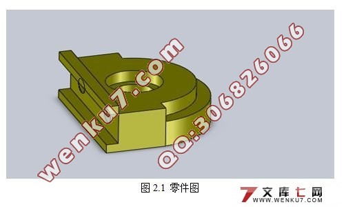
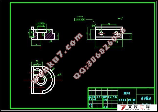
题目给出的零件活动是钳块(图2.1)。它的主要的作用是用作为一个普通零件,在机械各行业都必不可少,起支撑,固定等作用。
2.1.3 零件的工艺分析
如图1-1所示,零件更适合使用铣加工,结构简单,需加工的表面有:
(1)零件的上下平面,长74mm,高28mm下端面粗糙度Ra6.3;
(2)上端面向下至22mm处的台阶,保证粗糙度Ra12.5;
(3)上端面Ø28和Ø20H8的两个中心孔,粗糙度保证Ra6.3;
(4)两处螺纹孔,2-M10;
2.2 工艺分析及生产类型的确定
2.2.1 确定毛坯制造形式
零件的材料HT200。考虑到零件在工作中处于润滑状态,采用润滑效果较好的铸铁。由于年产量达到中批生产的水平,而且零件的轮廓尺寸不大,铸造表面质量的要求高,故可采用铸造质量稳定的,适合大批生产的金属模铸造。又由于零件的对称特性,故采取两件铸造在一起的方法,便于铸造和加工工艺过程,而且还可以提高生产率。
根据铸造的铸造件尺寸的大小和形状,且选用灰铸铁为材料,并且铸件的表面精度要求不是太高,结合生产效率和条件可选用砂型铸造
目 录
1 绪论 1
1.1 本课题研究的内容和意义 1
1.2 国内外的发展概况 1
1.3 本课题应达到的要求 1
2 设计内容 2
2.1 零件分析 2
2.1.1 零件的工艺性分析和零件图的审查 2
2.1.2 零件的作用 3
2.1.3 零件的工艺分析 3
2.2 工艺分析及生产类型的确定 3
2.2.1 确定毛坯制造形式 3
2.2.2 工艺规程的作用 4
2.2.3 基面的选择 4
2.2.4 工件表面加工方法的选择 4
2.2.7 确定切削用量及基本工时 10
2.3 夹具设计 23
2.3.1 问题的提出 23
2.3.2 定位基准的选择 23
2.3.4 切削力及夹紧力计算 25
2.3.6 夹具设计及操作简要说明 27
致谢 28
参考文献 29
附录 30
|


