预应力混凝土(55+100+55)m连续刚构桥上部结构设计(含CAD图)(任务书,开题报告,外文翻译,论文说明书30000字,CAD图11张)
摘 要
随着桥梁跨径的增大,预应力混凝土连续刚构桥凭借其良好的结构受力性能、新颖美观的外形和施工方法的快速发展,在国内外越来越受欢迎。
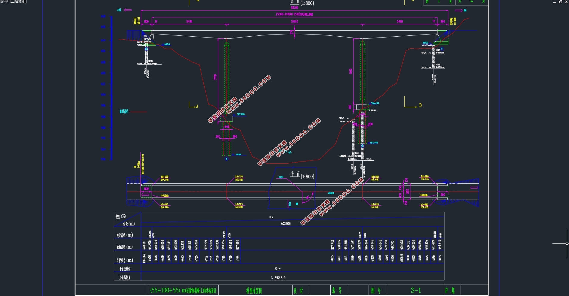
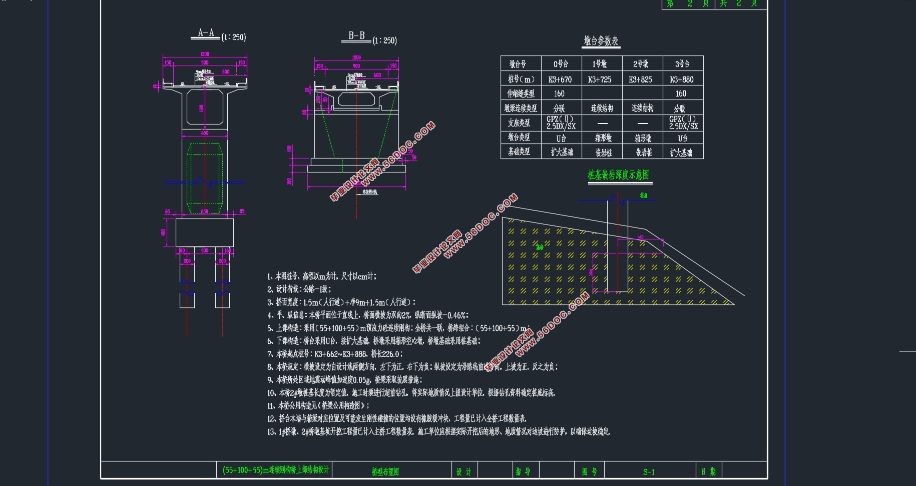
本次设计为(55+100+55)m公路连续刚构桥上部结构设计,全长210m,桥宽12m,分为1.5m人行道+净9m+1.5m人行道。箱梁断面采用单箱单室断面,箱梁顶板宽12m,底板宽6.5m,桥墩处为最大梁高6m,跨中为最小梁高2.5m,梁高按照二次抛物线变化。主梁的腹板从70cm变化到50cm,顶板厚度为28cm没有变化,底板从30cm变化到100cm,为二次方程变化。桥面横坡为双向2%,纵断面纵坡为-0.46%。设计荷载为公路-Ⅰ级荷载。
本次设计采用MIDAS/CIVIL有限元分析软件进行分析。桥梁上部结构共有72个单元,桥墩有19 个单元,左右主墩高度不一样,左墩高57m,右墩高48.5m。为更好模拟次内力对桥梁上部结构的影响,建模时桥墩按照实际长度建立。本桥采用的施工方法为悬臂现浇法,从0#块开始对称施工,先边跨合龙,然后中跨合龙。
基于MIDAS/CIVIL有限元模型,开展(55+100+55)m连续刚构桥纵向预应力筋设计,计算了桥梁各预应力筋的应力损失情况,明确了恒载、活载、温度荷载、支座沉降荷载以及预应力引起的桥梁结构内力分布特征。在承载能力极限状态和正常使用极限状态下,对正截面抗弯、抗剪及压应力、斜截面主压应力和桥梁变形等进行了验算,结果表明,所有截面内力和变形均通过验算,设计符合规范要求。
关键词:连续刚构桥;悬臂现浇;内力分析;结构验算
Abstract
With the increase of bridge span, the prestressed concrete continuous rigid frame bridge is gaining popularity both at home and abroad due to its rapid structural performance, novel appearance and construction methods.
This design is a (55 + 100 + 55) m highway continuous rigid frame bridge superstructure design, a total length of 210m, the bridge width of 12m, divided into 1.5m sidewalk + net 9m +1.5m sidewalk. The cross-section of box girder adopts a single-casing single-chamber section. The box girder roof is 12m wide and the floor width is 6.5m. The maximum beam height is 6m at the bridge pier and the minimum beam height is 2.5m in the midspan. The beam height changes according to the second parabola. The web of the main beam changed from 70cm to 50cm, the thickness of the top plate was 28cm without change, and the bottom plate changed from 30cm to 100cm, which was a quadratic equation change. The cross slope of the bridge is 2% in both directions, and the longitudinal slope of the longitudinal section is -0.46%. The design load is a road-I load.
This design uses MIDAS/CIVIL finite element analysis software for analysis. There are 72 units in the superstructure of the bridge, and there are 19 units in the pier. The heights of the left and right main piers are different. The left pier is 57m high and the right pier is 48.5m high. In order to better simulate the internal forces of the superstructure of the bridge, the modeling piers are built according to the actual length. The construction method adopted for this bridge is cantilever cast-in-place. Symmetrical construction starts from block #0.
Based on the finite element model of MIDAS/CIVIL, the design of longitudinal prestressed tendons of (55+100+55) m continuous rigid frame bridges was carried out. The stress loss of each prestressed tendon of the bridge was calculated, and the dead load, live load, temperature load, and The settlement load of the bearing and the distribution characteristics of the internal force of the bridge structure caused by the prestress. In the limit state of the bearing capacity and the limit of normal serviceability, the calculations of bending resistance, shearing and compressive stress of the normal section, principal compressive stress of the oblique section and bridge deformation were carried out. The results showed that the internal forces and deformations of all sections were checked and designed. Meet the specification requirements.
Key words: continuous rigid frame bridge; cantilever cast-in-place; internal force analysis; structure checking.
设计内容
本次设计任务为观音坡大桥,是一座预应力混凝土连续刚构桥,跨径布置为(55+100+55)m,主梁为变高度单箱单室截面,顶宽12.0m,底宽6.5m,三向预应力结构体系。施工方法为悬臂现浇法。设计汽车荷载:公路-Ⅰ级;设计基准期:100年。

目录
摘 要 Ⅰ
Abstract Ⅱ
第1章 绪论 1
1.1概述 1
1.2连续刚构桥的发展 1
1.3连续刚构桥的实例 1
1.4本次设计任务 2
1.4.1设计内容 2
1.4.2设计规划 2
第2章 基本资料与方案比选 3
2.1地形条件 3
2.2主要技术指标 3
2.3设计规范及标准 3
2.4方案比选 3
2.4.1桥梁比选的意义和任务 4
2.4.2桥型方案 4
第3章 桥跨总体布置及结构主要尺寸 7
3.1桥跨布置 7
3.2孔径划分 7
3.3桥梁上部结构拟定 7
3.3.1主梁截面形式与梁高拟定 7
3.3.2箱梁构造与细部尺寸 8
3.3.3桥面铺装 9
3.4 桥梁下部结构尺寸拟定 9
3.5 本桥使用材料 10
3.6 荷载资料 11
3.6.1 永久作用 11
3.6.2 可变作用 11
3.6.3 施工荷载 12
第4章 建模分析过程及桥梁内力计算 13
4.1概述 13
4.2模型的建立 13
4.2.1单元划分 13
4.2.2定义截面特性 15
4.2.3定义材料特性 15
4.2.4时间依存材料 16
4.2.5添加边界条件及定义边界组 17
4.2.6添加静力荷载 18
4.2.7添加支座沉降 18
4.2.8添加移动荷载 18
4.2.9定义施工阶段 19
4.3桥梁内力计算 24
4.3.1恒载内力计算 24
4.3.2汽车荷载内力计算 31
第5章 预应力钢筋估算与设计 37
5.1 预应力混凝土受弯构件设计流程 37
5.2 预应力钢筋面积估算 37
5.2.1计算原理 37
5.2.2面积估算 40
5.3预应力钢筋布置原则 42
5.3.1纵向预应力钢筋布置原则 42
5.3.2横、竖向预应力钢筋布置原则 46
5.4预应力损失的估算 50
5.4.1 锚具变形、钢束回缩和接缝压缩引起的应力损失σL1 50
5.4.2 预应力筋与管道壁之间摩擦的应力损失σL2 51
5.4.3混凝土弹性压缩引起的应力损失σL4 52
5.4.4钢筋松弛引起的应力损失σL5 52
5.4.5混凝土的收缩和徐变引起的应力损失σL6 53
5.4.6 有效预应力的计算 58
5.5 有效预应力的计算 59
第6章 次内力计算及荷载组合 62
6.1温度次内力 62
6.1.1整体升温和降温 62
6.1.2局部升温和降温 65
6.2基础沉降引起的次内力 69
6.3预应力引起的次内力 71
6.4收缩徐变引起的次内力 73
6.5荷载组合 76
6.5.1承载能力极限状态的荷载组合 77
6.5.2正常使用极限状态的荷载组合 79
第7章 主要截面的验算 83
7.1承载能力极限状态的验算 83
7.1.1主梁正截面抗弯强度的验算 83
7.2主梁正截面抗裂性验算 85
7.3主梁斜截面抗裂性验算 86
7.4 混凝土构件应力验算 88
7.4.1 使用阶段正截面主梁压应力验算 88
7.4.2 使用阶段主梁斜截面主压应力验算 89
7.4.3主梁受拉区钢筋拉应力验算 90
7.4.4施工阶段混凝土法向压应力验算 92
7.5挠度验算 94
7.5.1中跨挠度验算 94
7.5.2边跨挠度验算 94
第8章 总结 95
参考文献 96
|