全长140m预应力混凝土一联四跨连续梁桥设计(35m+35m+35m+35m)(含CAD图)(任务书,开题报告,外文翻译,论文计算书17000字,CAD图28张)
摘 要
本设计是根据设计任务书的要求和《公路桥规》的规定,对浙江温州鳌江四桥引桥进行方案比选和设计的。连续梁桥是工程上广泛使用的一种桥型,它不但具有可靠的强度,刚度及抗裂性,而且具有行车舒适平稳,养护工作量小,设计及施工经验成熟的特点。设计一座梁桥必须从桥跨布设,尺寸拟定,钢束布置以及施工方法等方面综合考虑,还要充分考虑设计参数和环境影响。本设计是一联四跨连续梁桥,截面形式为单箱四室,纵向等截面;施工方式是悬臂(挂篮)施工整体现浇。该设计首先进行恒载、活载及次内力的计算,在此基础上进行荷载组合,绘制弯矩和剪力包络图;其次,根据短期效应组合配置预应力钢筋,并进行预应力损失的计算;最后,对该连续梁桥进行验算,是否满足设计要求。下部结构采用柱式墩,墩台采用桩基础,并分别对桥墩和桩基础进行了计算和验算。
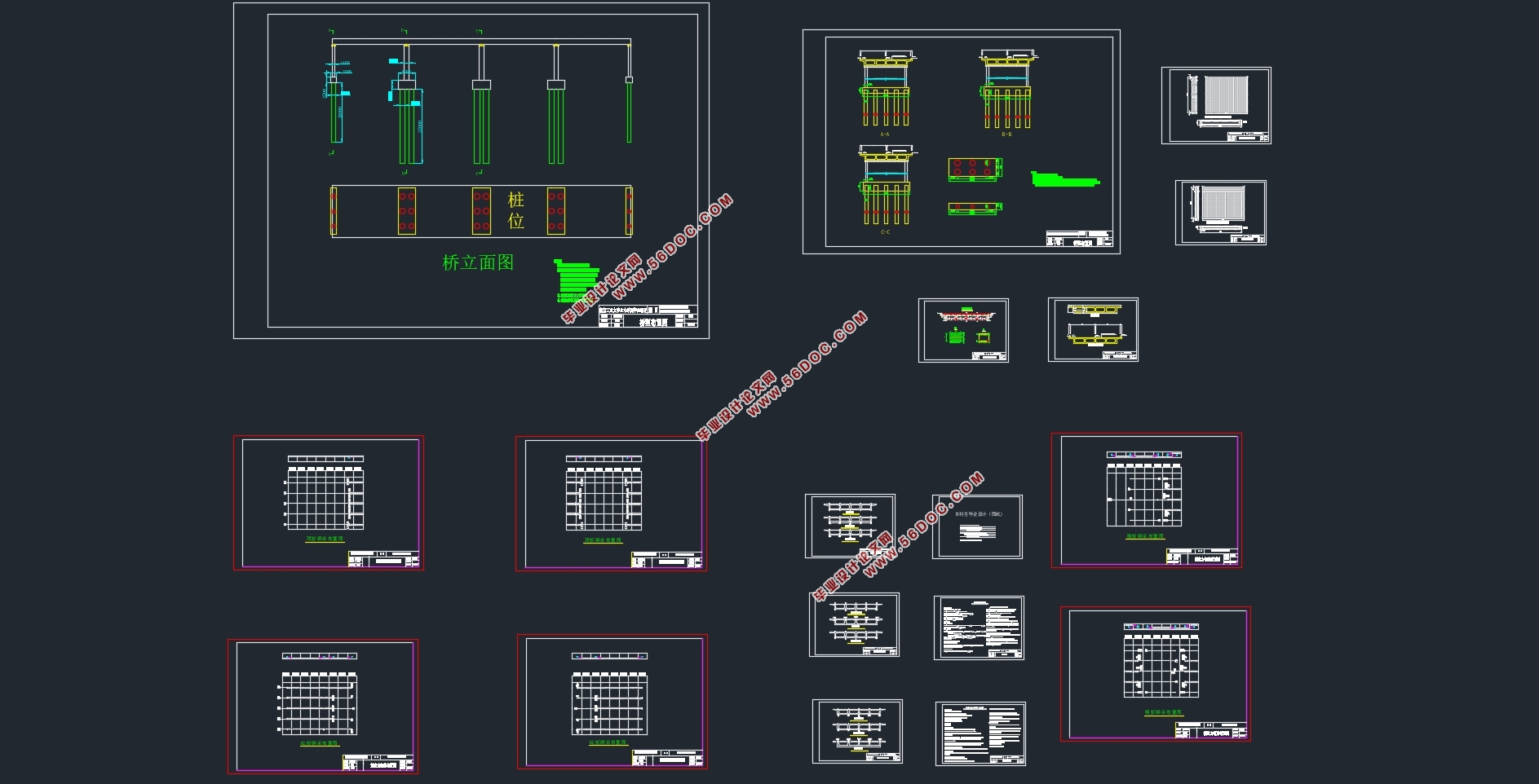
本设计全部设计图纸采用计算机辅助设计绘制,计算机编档、排版,打印出图及论文。
关键词:设计 连续梁桥 悬臂施工(挂篮) 预应力
The design of Zhejiang Wenzhou Aaojiang River four bridge approach bridge of prestressed concrete continuous girder bridge
Abstract
This design according to the provisions of the design requirements of the task and the "bridge", scheme selection and design of ZhejiangWenzhou Aojiang River four bridge approach. Continuous girder bridge is a bridge is widely used in engineering, it not only has thereliable strength, stiffness and crack resistance, but also hascomfortable driving stability, small maintenance workload, the design and construction features of mature experience. The design of a bridgefrom the bridge to layout, size of the development, the layout of the steel beam and the construction methods, but also give full consideration to the design parameters and environmental impact. This design is a 4-span continuous beam bridge, single box section,longitudinal section; construction mode is the cantilever (basket)construction of cast-in-place. The first design of dead load, live load calculation and secondary internal force, load combinations on the basis of drawing, bending moment and shear force envelope diagram;secondly, according to the short-term effects of combinations ofprestressed reinforcement, and calculated the prestress loss; finally,the checking of the continuous beam bridge, if meet the design requirements. The substructure adopts pier, the pier with pile foundation, and the pier and pile foundation were calculated and checked.
The design of all the drawings by drawing the computer aided design,computer filing, typesetting, printing out the map and the.
Keywords: Design Continuous girder bridge
Cantilever
Cantilever construction (basket)
Prestressed
标准跨径
鳌江四桥引桥连续梁桥长140m。根据设计要求,此桥设计要求采用等截面连续箱梁结构形式。通过计算,确定跨径布置如下:
35m+35m+35m+35m=140m

目 录
第一章 方案设计...................................................1
1.1 跨径布置...................................................1
1.2 顺桥向设计.................................................2
1.3 横桥向设计.................................................3
第二章 恒载计算...................................................6
2.1 节段划分及截面几何要素计算.................................6
2.2 一期恒载计算...............................................7
2.3 二期恒载计算...............................................8
2.4 总恒载计算.................................................9
第三章 活载计算..................................................11
3.1 汽车荷载 .................................................11
3.2 最大,最小弯矩及其对应的剪力计算..........................13
3.3 最大,最小剪力及其对应的弯矩..............................18
3.4 人群荷载..................................................24
第四章 次内力计算................................................27
4.1 温度次内力计算............................................27
4.2 支座沉降次内力计算........................................31
第五章 内力组合及内力包络图......................................34
5.1 短期效应组合..............................................34
5.2 长期组合..................................................35
5.3 基本组合..................................................36
5.4 包络图....................................................37
第六章 预应力筋的计算与布置......................................41
6.1 原理与方法................................................41
6.2 预应力筋的配置............................................41
6.3 钢束布置..................................................47
第七章 净截面及换算截面几何特性计算..............................55
7.1 概述......................................................55
7.2 净截面几何性质计算........................................55
7.3 换算截面性质计算..........................................59
第八章 预应力损失及有效预应力计算................................62
8.1 控制应力及有关参数计算....................................62
8.2 摩擦损失 ......................................................62
8.3 锚具回缩损失 ...................................................66
8.4 弹性压缩损失 ...................................................70
8.5 应力松弛损失 ...................................................71
8.6 收缩徐变损失 ...................................................71
8.7 预应力损失组合及有效预应力计算.....................................73
第九章 承载能力极限状态验算......................................75
9.1 正截面承载能力验算........................................75
9.2 斜截面抗剪承载力验算......................................78
第十章 正常使用极限状态验算......................................81
10.1 抗裂验算..................................................81
第十一章 持久状况和短暂状况应力验算...............................83
11.1 持久状况截面混凝土法向应力验算...........................83
11.2 短暂状态应力验算.........................................84
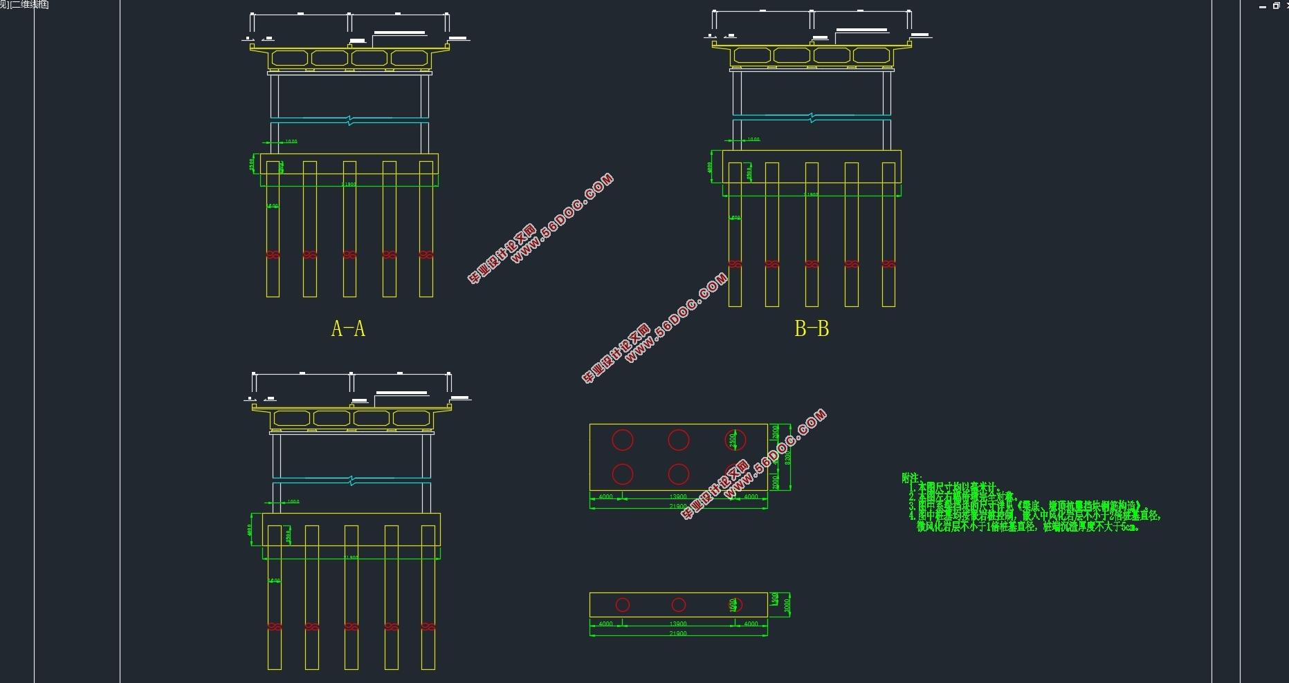
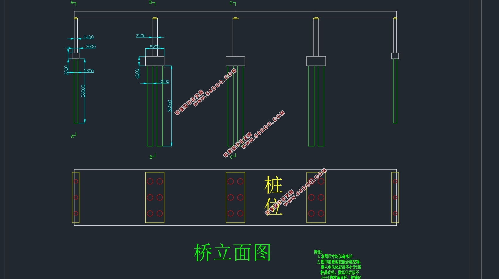
第十二章 墩及桩基础的设计与计算...................................86
12.1 支座.....................................................86
12.2 墩身设计与验算...........................................87
12.3 承台设计.................................................89
12.4桩基础设计...............................................89
参考文献..........................................................92
致 谢.............................................................93
|