重庆市9200平米某综合大厦暖通空调设计(含CAD图)(任务书,开题报告,外文翻译,计算说明书17000字,CAD图纸15张,答辩PPT)
摘 要
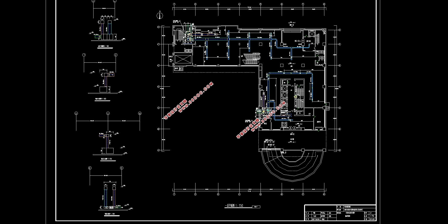
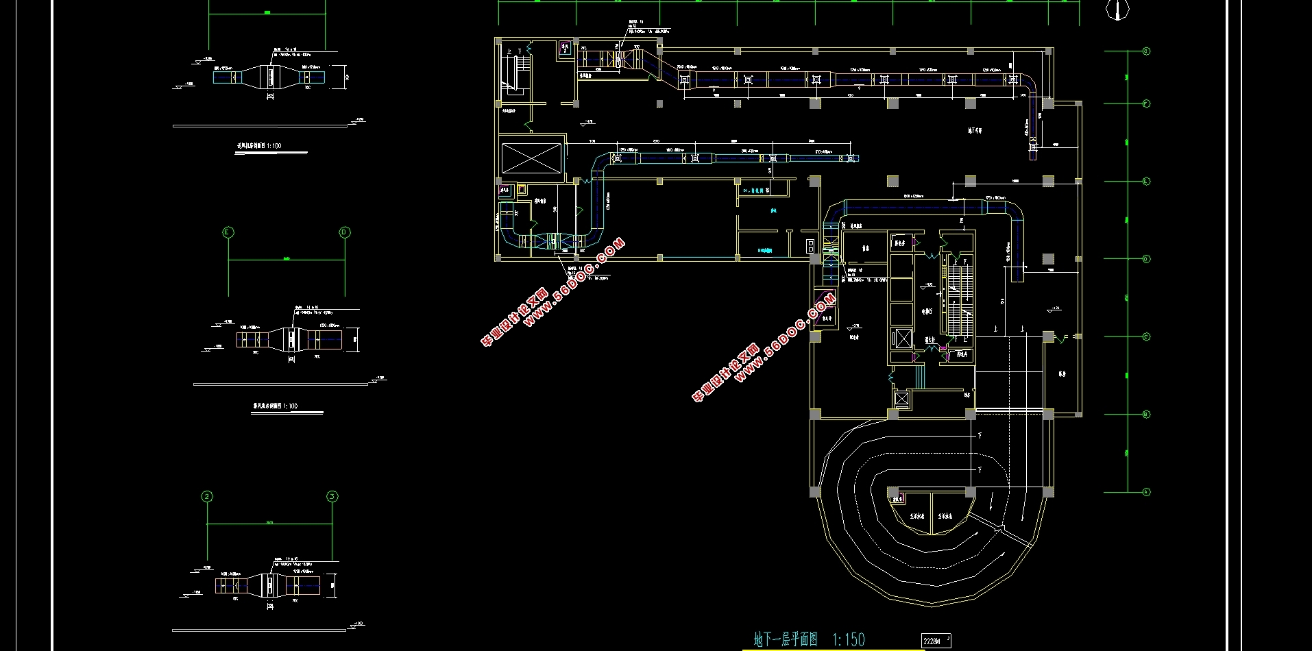
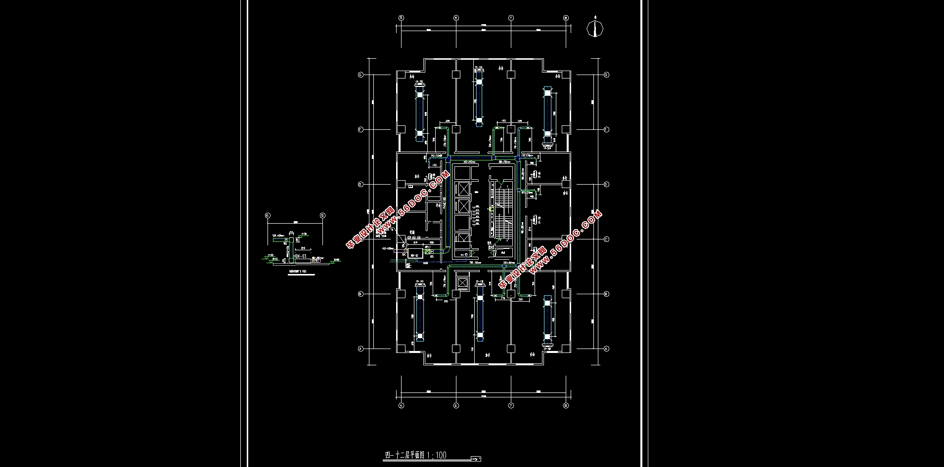
本建筑为重庆市某综合大厦暖通空调设计,总建筑面积9200m2。地下一层,地上十二层,空调设计范围为地下一层至地上六层。一层到二层为商场,三层为餐厅,四层为办公室。地下一层为车库。
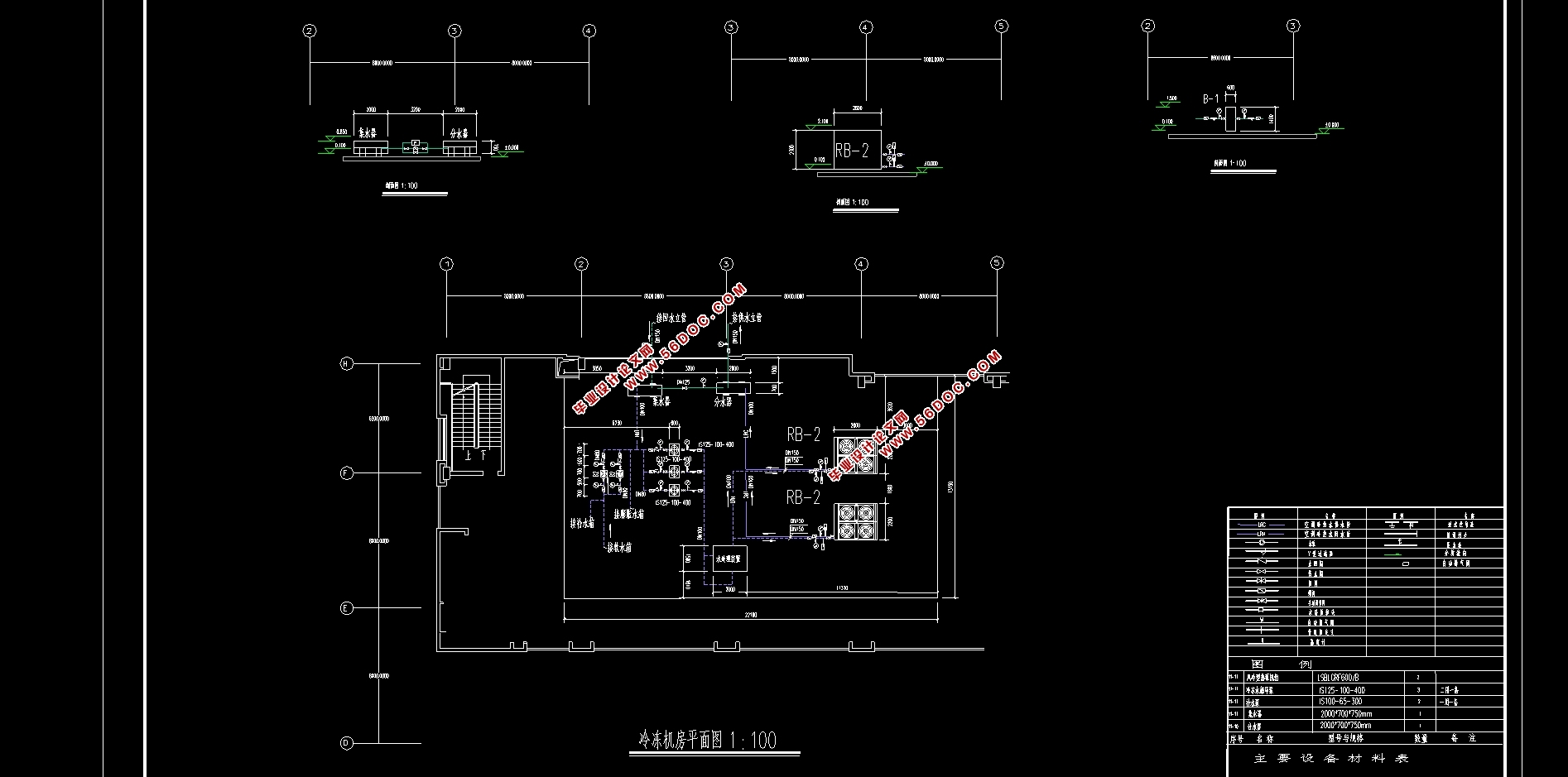
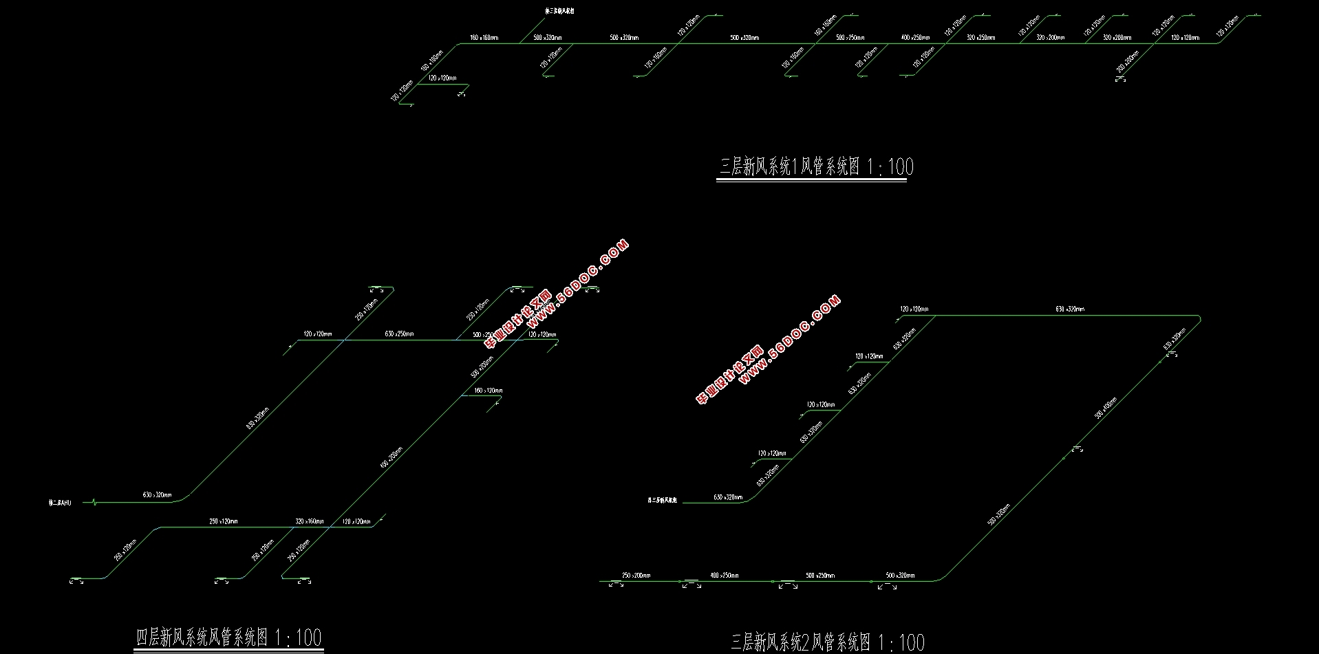
本设计负荷计算采用冷负荷系数法计算冷负荷,地上一二层采用全空气系统,三至六层的餐厅办公室采用风机盘管加新风系统。空调水系统采用闭式,异程,两管制,变流量,一次泵系统。本工程采用空气源热泵作为冷热源,选用两台海尔牌LSBLGRF630/B螺杆型风冷热泵机组,机房设置在屋顶。地下单独设置防排烟系统,电梯间设置加压送风系统防排烟。
关键词:全空气系统风机盘管系统独立新风系统 加压送风
HVAC Design of a Complex Building in Chongqing
Abstract
This building is a HVAC design for a complex building in Chongqing, with a total floor area of 9200m2. The air conditioning design ranges from one floor underground to six floors above ground. From the first floor to the second floor, there are shopping malls, restaurants on the third floor and offices on the fourth floor. The underground floor is a garage.
In this design, the cooling load is calculated by the cooling load coefficient method. The whole air system is used on the first and second floors above ground, and the fan coil unit plus fresh air system is used in the restaurant offices on the third and sixth floors. Air conditioning water system adopts closed, off-road, two-pipe, variable flow, primary pump system. In this project, air source heat pump is used as cold and heat source. Two Haier LSBLGRF630/B screw air-cooled heat pump units are selected. The machine room is set on the roof. A smoke control and exhaust system is set up separately in the underground, and a pressurized air supply system is set up in the elevator room to prevent and exhaust smoke.
Key words: all-air fan-coil system independent fresh air system pressurized air supply
工程概况
本综合楼系重庆市某单位兴建的一座多功能综合性民用建筑,地上12层,地下一层,建筑高度62m,建筑面积9200m2,地下室为车库,一二层为商场、商务中心、,三层为餐厅,四~十二层为办公室。
目录
第一章 空调负荷计算 1
1.1 工程概况 1
1.1.1 围护结构参数 1
1.1.2 照明功率 1
1.1.3 电气设备使用功率 2
1.1.4 人员密度 2
1.1.5 空调使用时间 2
1.1.6 室外气象参数 3
1.1.7 空调室内设计参数 3
1.1.8 设计新风量 3
1.1.9人体的散热和散湿 3
1.2.5 照明负荷 4
1.2.6 设备负荷 4
1.3 室外的冷负荷的计算方法 5
1.3.1 通过外墙和楼板传热形成的逐时冷负荷 5
1.3.2 通过窗户传热形成的逐时冷负荷 5
1.3.3 窗户日射得热行程的冷负荷 5
1.3.4 商场冷负荷计算 6
1.3.5 一层商场冷负荷汇总 8
2.1 热负荷计算 9
2.2 湿负荷及热湿比计算 9
第二章 空调方案分析确定 11
2.1 风系统设计 11
2.1.1 空调系统的划分原则 11
2.1.2 方案比较 11
2.2 水系统设计 14
2.2.1 方案比较 14
2.3 本设计的系统划分与确定 15
第三章 空调送风量、冷量、水量计算及设备选型 17
3.1全空气系统送风量及冷量计算 17
3.2.1 风机盘管+新风系统送风量及冷量计算 18
3.2空调设备选型 20
3.2.1组合式空调机组选型 20
3.2.2 风机盘管选型 20
3.2.3 新风机组选型 21
第四章 气流组织计算 22
4.1散流器送风房间 22
4.1.1空调系统一商场 22
4.1.2 空调系统二餐厅(送新风) 23
4.2 侧送风房间 24
第五章 风管水力计算 26
5.1 风系统设计任务与方法 26
5.2 全空气系统风管水力计算 26
5.2.1 送风管水力计算 26
第六章 水系统水力计算 28
6.1 管材选择和连接 28
6.2 管径的确定 28
6.2.1 沿程阻力 29
6.2.2 局部阻力及局部阻力系数 30
6.3 冷凝水管路的设计计算 31
第七章 建筑通风和防排烟 33
7.1通风设计 33
7.1.1 通风管道设计方案 33
7.1.2通风管道水力计算 33
7.2 排烟设计 34
7.3防烟设计 35
7.4通风及防排烟设备选型 35
7.4.1 送风风机选型 35
7.4.2 排风风机选型 36
7.4.3 排烟风机选型 36
第八章 冷热源机房设备选择 37
8.1 热泵机组的选型 37
8.2 水力计算 37
8.2.1冷热水循环系统水力计算 37
8.2.2冷热水泵的选择 38
8.3膨胀水箱设计选择 39
第九章 消声减震与保温防腐 40
9.1 消声设计 40
9.2 减振设计 40
9.3 保温设计 40
9.4 防腐设计 41
|