埃塞俄比亚保险大楼20m深基坑支护设计及邻近已有建筑基础变形控制(含CAD图)(任务书,开题报告,论文计算书23000字,CAD图6张)
摘要
进入本世纪以来,我国城市建设的步伐一直在稳步推进,越来越多的高楼彰显着我国现代化建设的突出成果。大城市以其突出的优势吸引着越来越多的人口向城市迁移,在有限的土地资源下,要容纳并满足人们的生活,建筑物不断往纵深化发展,同时地下空间的开发利用成为越来越多工程项目的重点。更高的建筑同时意味着更高的上部结构荷载,这对于基础强度无疑是一个挑战,基坑越来越向深化发展。与此同时,一般高层建筑均位于人口密集、周边建筑复杂的地段,基坑的施工过程应尽量减少最好避免对周边环境的恶性影响。如何在深基坑开挖与施工过程中减少基坑变形,控制周围临近建筑的影响就成为了当前深基坑发展的一个重要课题。基于此,本设计以埃塞俄比亚雅迪斯某保险大楼工程项目为背景,仔细调查了周边场地概况与上部结构形式,最终采用先导置入式的基坑开挖方式对该工程的基坑开挖过程进行了设计,利用理正深基坑软件对支护结构进行了设计计算。以该项目为背景,对开挖过程利用MIDAS/GTS NX建立有限元模型,对各个工况下基坑四周土体变形量、支护结构的位移、坑底隆起、土层应力进行了数值模拟分析,模拟结果显示设计方案满足建筑规范的技术要求,从而验证了设计方案具有合理性。本设计主要完成的内容:
(1)调查了解建筑场地的工程地质状况,阅读结构专业图纸与现场现状图,详细了解场地四周的环境与周边建筑情况,查阅相关工程实例并确定基坑开挖与支护方案。
(2)利用理正深基坑7.0软件,选择了基坑开挖过程中的两个典型断面进行单元计算,初步分析开挖过程中的变形、内力、抗隆起、抗倾覆等是否满足规范要求。结果标明,该设计方案下产生的最大位移为9.07mm,满足规范要求,桩身的最大弯矩与建立均在材料设计抗力以内。
(3)利用MIDAS/GTS NX对基坑施工过程建立数值分析模型,采用有限元的方法分析开挖过程产生的变形与位移,结果显示:在该支护方案下,基坑支护结构所产生的最大水平位移为8mm左右,周边场地开挖影响下产生了沉降,最大沉降量为10mm。通过查阅当前基坑设计规范,开挖引起的变形与沉降满足设计规范要求。
(4)根据基坑开挖与支护方案,确定基坑施工所需机械设备与基坑的施工方案,设计基坑施工监测方案。
关键词:深基坑;支护;变形控制;MIDAS/GTS NX
Abstract
These years have witnessed the rapid economic development, urban construction is also developing and progressing. However, due to the limited land resources available, the current building is gradually developing to a higher level, and more and more underground space is being developed. The construction of high-rise buildings has higher requirements for foundations, and the excavation of foundation pits is deeper and deeper. Meanwhile, the general high-rise buildings are located in densely populated areas with complex surrounding buildings. The construction process of the foundation pits must not have a malignant impact on the surrounding environment. To find out ways toreduce the deformation of the foundation pit and the influence on the nearbystructures during the excavation has become an significanttopic in the development of the deep foundation pit engineering.With this background, this design is based on an engineering project of an insurance building in Addis Ababa, Ethiopia, through reading the geotechnical geological survey report, the architectural superstructure design drawing and overviewing the surrounding site, the foundation pit excavation process was designed in the pilot-in-place foundation pit excavation method., and then the internal force of the supporting structure wascalculatedby using the software of the deep foundation pit called LIZHENG.The finite element model of foundation pit excavation process was established by MIDAS/GTS NX. The numericalanalysis result of the soil deformation around the foundation pit,the supporting structure’s displacement, the bottomdeformationof the pit and the soil stress during the excavation were carried out. The results showed that the design meets the technical requirements of the building code, thus verifying the rationality of the design. The main content of this design as follows:
(1)The engineering geological conditions around the site and the structural form of the superstructure was analyzed,the environment around the site and surrounding buildings was surveyed.By consulting relevant engineering examples,the methods of the foundation pit excavation and support was determined.
(2) Using the software of Lizheng Deep Foundation Pit 7.0, the finite element simulation analysis of the foundation pit supporting structure was carried out to analyze whether the deformation, internal force, anti-uplifting and anti-overturning in the excavation process meet the requirements of the specification. The results showed that the maximum displacement generated under the design scheme is 9.07mm, which meets the requirements of the specification, and the maximum bending moment and establishment of the pile body are all within the material design resistance.
(3) Using MIDAS/GTS NX , a finite element model for the foundation pit construction processwas established, and the deformation and displacement generated during the excavation processwas analyzed. The results showed that under the support scheme, the maximum horizontal displacement of the foundation pit is about 8mm, and the maximum settlement of surrounding buildings is about 10mm, which meets the requirements of design specifications.
(4) According to the foundation pit excavation and support plan,the construction plan for the foundation pit excavation and the mechanical equipment required isdetermined, and the content of the foundation pit construction monitoring and the arrangement of the monitoring pointsis determined as well.
Key words: deep foundationpit; supporting structure; deformation control; MIDAS/GTS NX
工程概况
场地周边情况
拟建大楼位于亚迪斯亚巴贝非洲大道,北侧为平房与空地,南侧有一栋四层建筑,西侧为一栋办公用平房与一栋六层建筑,东侧为机场大道。因此在基坑开挖过程中必须严格控制因开挖产生的地面位移。拟建建筑物地面以上17层,地面以下3层,采用框架与剪力墙相结合的结构,占地面积约为48m×31m,开挖场地呈矩形,开挖深度约为20m。采用阀形基础作为基础系统,基坑开挖深度为19.6m,不考虑地下水作用。
该工程的西北侧场地较为开阔,为平房与空地,空地在施工过程中尽量转移其上部堆载,隔壁平房层高为2层,在施工过程中不考虑平房荷载的影响。场地东北侧有一4层建筑,在施工过程中应考虑其上部结构荷载作用以及开挖过程中的基础沉降,取其荷载为80kPa。场地西南侧建筑群较为密集,现有建筑为两栋办公用房,层高分别为两层与六层,故在施工过程中仅考虑办公用房1上部结构荷载产生的影响,取其荷载值为120kPa。场地东北侧为非洲大道,该道路是亚迪斯北巴城市内的主要道路,故施工过程中为保证该道路的正常通行,减小对城市交通的压力,应控制好地表的沉降。
基础形式
考虑到地下条件、现场和实验室试验结果以及预期结构荷载,最大无系数柱荷载约为7358.83kN,总无系数柱荷载约为195606.7KN。由于需要修建三层地下室,宜采用筏形基础作为基础系统。
目录
第一章绪论 1
1.1 选题背景及意义 1
1.1.1 选题背景 1
1.1.2 选题意义 1
1.2 国内外研究现状 2
1.2.1 基坑工程开挖与支护技术的发展 2
1.2.2 基坑数值模拟研究现状 3
1.3 工程概况 3
1.3.1 场地周边情况 3
1.3.2 场地周边荷载分布 4
1.3.3 基础形式 4
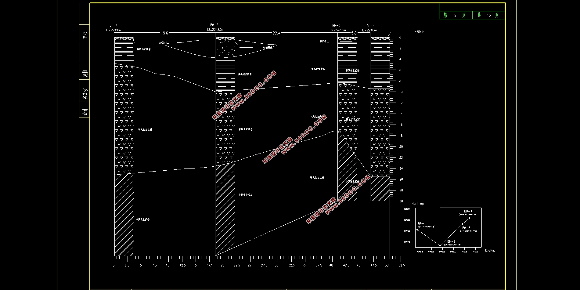
1.4 地质条件 5
1.5 拟解决的问题 6
第二章深基坑开挖与支护方案设计 7
2.1 基坑开挖与支护方案设计 7
2.1.1 明挖法+地下连续墙与锚杆支护 7
2.1.2 分层逆作法+地下连续墙与锚杆支护 7
2.1.3 先导置入式开挖+地下连续墙与锚杆支护 8
2.1.4 方案比选 8
2.2 基坑开挖与支护结构参数的选取 9
第三章基坑支护结构设计计算书 10
3.1 钢板桩+内支撑支护结构计算书 10
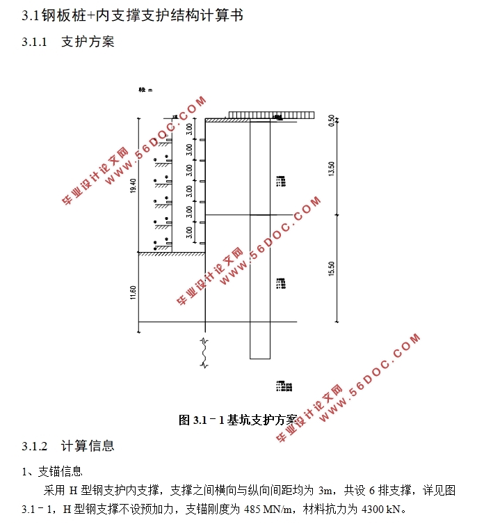
3.1.1 支护方案 10
3.1.2 计算信息 10
3.1.3 内力位移包络 12
3.1.4 截面抗弯验算 17
3.1.5 整体稳定性验算 17
3.1.6 抗倾覆稳定性验算 18
3.1.7 抗隆起验算 23
3.1.8 嵌固段反力验算 24
3.2 地下连续墙+锚杆支护结构计算书 25
3.2.1 支护方案 25
3.2.2 计算信息 26
3.2.3 内力位移包络图 27
3.2.4 截面计算 32
3.2.5 整体稳定性验算 34
3.2.6 抗倾覆稳定性验算 35
3.2.7 抗隆起验算 39
3.3 本章小结 41
第四章基于MIDAS/GTSNX数值模型的建立与结果分析 42
4.1 MIDAS/GTSNX简介 42
4.2 数值模型的建立与施工阶段划分 43
4.2.1 土体本构模型的选取 43
4.2.2 实体模型建立 43
4.2.3 模型材料参数设置 45
4.2.4 网格划分 45
4.2.5 施工阶段的划分 46
4.3 基坑位移分析 48
4.4 基坑应力分析 50
4.5 围护结构位移分析 52
第五章施工方案设计 54
5.1 钢板桩+内支撑施工方案设计 54
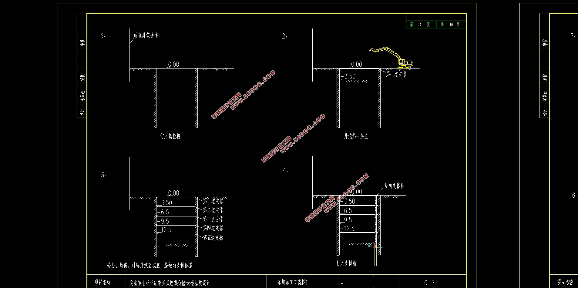
5.1.1 施工流程 54
5.1.2 施工机械 54
5.1.3 主要施工方法 54
5.2 地下连续墙+锚杆施工方案设计 56
5.2.1 施工流程 56
5.2.2 施工机械 56
5.2.3 主要施工方法 56
第六章基坑施工质量检测方案 58
6.1 监测目的 58
6.2 监测内容 58
6.3 监测方法与监测点的布置 59
第七章总结与展望 64
7.1 总结 64
7.2 展望 64
|