微型车悬架设计(英文版)(含CAD零件图装配图)(任务书,开题报告,外文翻译,文献摘要,论文说明书英文版8000字,CAD图6张)
Abstract
With the rapid development of the automobile industry, people have put great demands on the safety, comfort and stationariness of automobile power, and the improvement of automobile suspension can meet people's requirements. At the same time, there are more and more cars in cities, more and more congested roads and more compact parking Spaces. The appearance of minicar is also driven by the fact. Therefore, it is of practical significance to design the suspension of minicar.
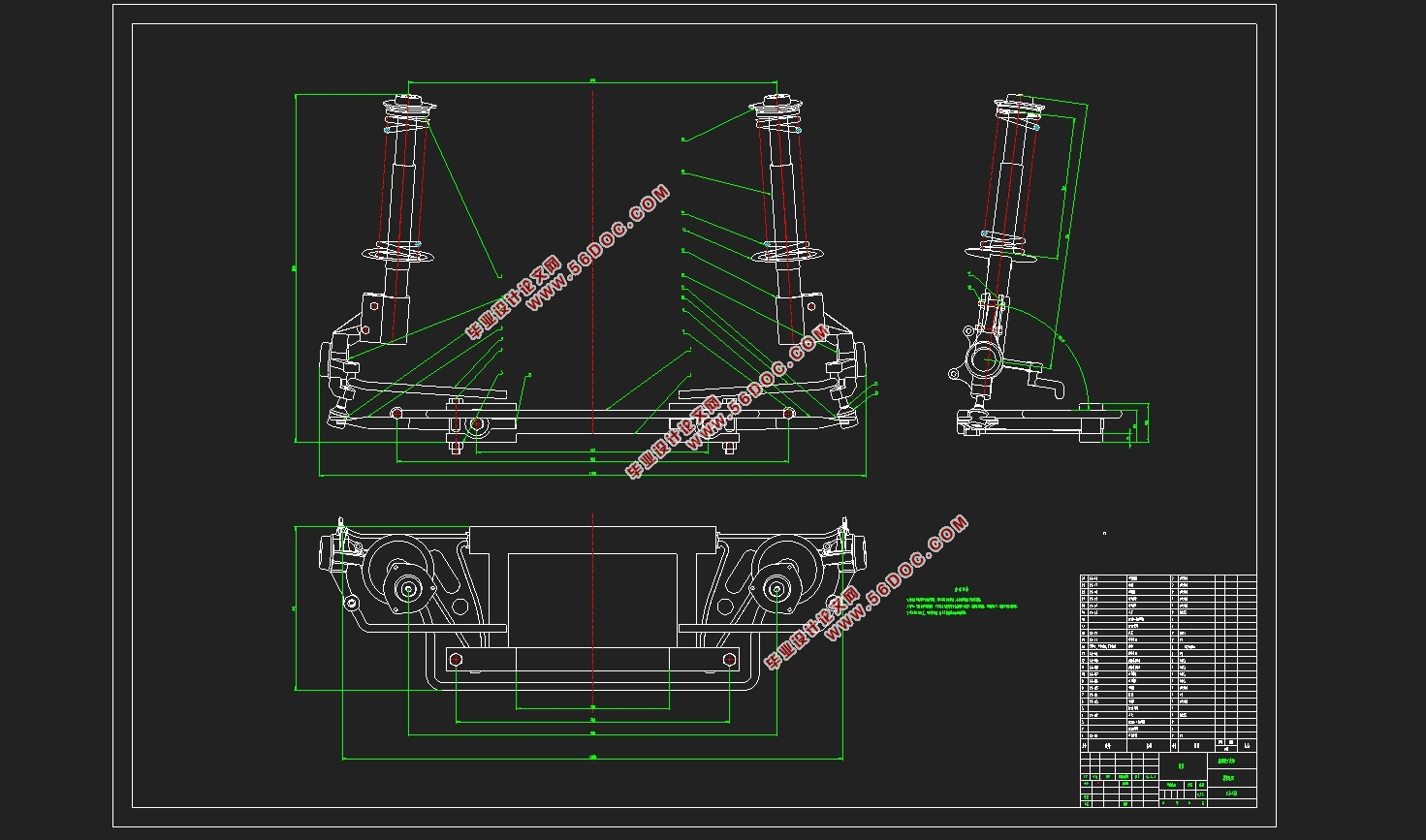
The theme of my design is: the structural design of the front and rear suspension system of micro cars. The type of front suspension is macpherson independent suspension.
The main function of suspension is to transfer all forces and torques between the wheel and the body, such as supporting force, braking force and driving force, etc., and to ease the impact load from uneven road surface to the body, attenuation of the vibration caused by this, to ensure the comfort of passengers, reduce the dynamic load of goods and vehicles themselves. Its main task is to transfer all forces and torques acting between the wheel and the frame (or body); Ease the impact load from the road to the frame (or body), attenuate the vibration of the bearing system, and ensure the ride smoothness of the car; To ensure that the wheels in uneven road surface and load changes when the ideal motion characteristics, to ensure the stability of the vehicle control, so that the car to obtain high-speed driving ability.
When the car is driving on uneven road surface, the elastic action of the suspension makes the car produce vertical vibration. In order to rapidly attenuate this vibration and restrain the resonance of the car body and wheel, reduce the amplitude of the wheel, the suspension should be equipped with shock absorber, and make it have reasonable damping. By using the damping effect of shock absorber, the amplitude of automobile vibration decreases continuously until the vibration stops.
In order to satisfy the vehicle with good ride comfort, the natural frequency of the vibration system composed of spring mass and elastic components should be in the appropriate frequency band and as low as possible.The natural frequency matching of the front and rear suspension should be reasonable. For passenger cars, the natural frequency of the front suspension should be slightly lower than that of the rear suspension, and try to avoid the suspension hitting the frame (or body).In the case of the mass change on the spring, the height change of the car should be small, so the nonlinear elastic suspension should be adopted.
To choose the correct suspension scheme and parameters, in the wheel, under the jump, so that the kingpin positioning Angle changes little, wheel movement and guide mechanism movement to coordinate, avoid the front wheel shimmy; When the car is turning, it should be slightly less characteristic.
Suspension is related to various performance of automobile. In order to meet these performance, the design requirements of suspension are as follows:
1) ensure good ride comfort.
2) have the ability to attenuate vibration properly.
3) ensure the vehicle has good handling stability.
The 3d model was designed by caita, and the feasibility analysis of the model was carried out by ansys, and the results were obtained.
In this graduation design, McPherson independent suspension with simple structure and low cost is selected to improve the smoothness and comfort when accelerating and braking and ensure the stability when driving in a straight line. It can be known that the current McPherson independent suspension is widely used.
Key words: McPherson; Independent suspension; CATIA; ANSY
reference model parameters
In this design, the manual comfort model of panben 2018 1.4l is selected as the reference.Its specific parameters are as follows:
Length (mm) 3730
Width (mm) 1650
Height (mm) 1530
Wheelbase (mm) 2410
Front wheelbase (mm) 1420
Rear wheelbase (mm) 1430
Packing weight (kg) 1020
Maximum power (KW) 74
Maximum torque (N•m) 135
Front tyre specification 165/60 R14
Rear tyre specification
165/60 R14
Drive way Lead precursor
Front suspension type McPherson independent suspension
Rear suspension type Torsion beam dependent suspension
Maximum torque speed 4000
Size parameters Wheelbase (mm) 2410
Wheel base Front wheel (mm) 1420
Rear wheel (mm) 1430
Quality parameters Axial load distribution no-load Front axle (kg) 660
Rear axle (kg) 630
Full load Front axle (kg) 780
Rear axle (kg) 885

目录
Chapter 1 The introduction 1
1.1 overview of suspension 1
1.2 introduction to suspension parts 2
1.2.1 elastic element 2
1.2.2 shock absorber 2
1.2.3 guiding mechanism 2
1.2.4 transverse stabilizer bar 3
Chapter 2 suspension design calculation 4
2.1 main technical parameters 4
2.1.1 reference model parameters 4
2.1.2 natural vibration frequency 5
2.1.3 suspension static deflection 6
2.1.4 suspension dynamic deflection 7
2.1.5 suspension stiffness 7
2.2 coil spring design 8
2.2.1 working principle of spiral spring 8
2.2.2 design of main parameters of spring 8
2.3 shock absorber design 11
2.3.1 working principle overview about shock absorber 11
2.3.2 selection of main performance parameters about shock absorber 12
Chapter 3 design of guide mechanism and lateral stabilizer bar 15
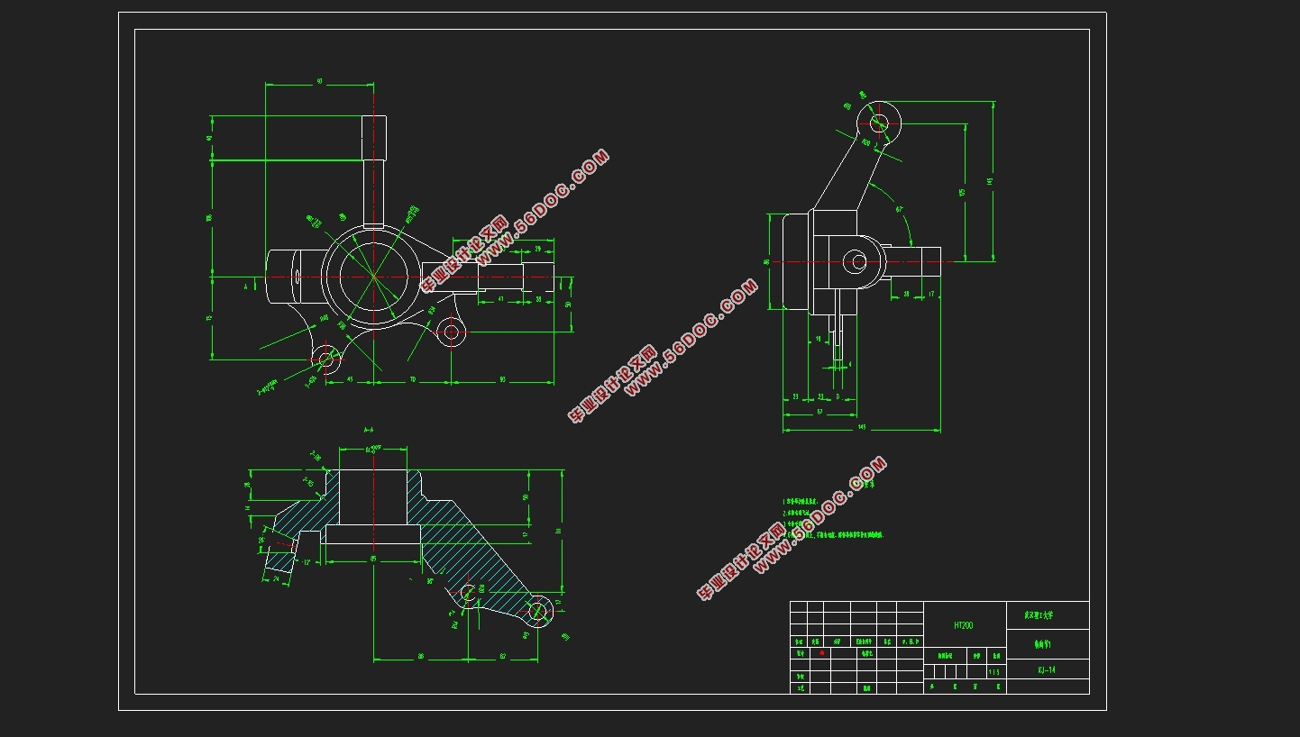
3.1 design of guiding mechanism 15
3.1.1 design requirements of guiding mechanism 15
3.1.2 McPherson independent suspension schematic diagram 16
3.1.3 force analysis of guiding mechanism 17
3.1.4 wheel positioning parameters 17
(1) wheelbase 17
(2) wheel camber Angle 18
(3) wheel front beam 19
3.2 design of transverse stabilizer bar 19
3.2.1 working principle of transverse stabilizer bar 19
3.2.2 determination of transverse stabilizer bar parameters 19
Chapter 4 McPherson suspension finite element modeling 22
Chapter 5 conclusion 27
Reference 28
The appendix 30
Thanks 34
|