升降机控制系统的PLC应用研究(含接线图,电路图,梯形图)(任务书,开题报告,进度检查表,毕业论文19000字)
摘 要
PLC可编程序控制器是以微处理器为基础,综合了计算机技术、自动控制技术和通讯技术发展而来的一种新型工业控制装置。它具有结构简单、编程方便、可靠性高等优点,已广泛用于工业过程和位置的自动控制中。据统计,可编程控制器是工业自动化装置中应用最多的一种设备。可编程控制器将成为今后工业控制的主要手段和重要的基础设备之一,PLC、机器人、CAD/CAM将成为工业生产的三大支柱。由于PLC具有对使用环境适应性强的特性,同时其内部定时器资源十分丰富,所以很多公司都在使用PLC来控制生产线的运作,比如生产显示器、电视机就利用到了升降机。利用升降机可以把显示器运送到加温层,运送包装线,在运送的过程中就可以利用PLC控制,进行测试、检验。最后实现科学运作。
本文主要是升降机控制系统的PLC应用研究。主控系统采用FX2N48MR-001PLC为控制核心,结合模拟量输出模块FX2N-2DA,并设计了施工升降的理想速度曲线。PLC系统完成了所有I/0信号和上位机串口通信信号的接收,根据其内部设计程序进行集中运算处理,实现了对液压施工升降机的控制系统的逻辑信号及速度控制。另外,还根据控制系统要求,设计了控制系统主回路、安全运行电路、电液比例控制回路等。
关键词:升降机;PLC;程序;设计
Abstract
PLC programmable logic controller is a microprocessor based on a combination of computer technology, automatic control technology and communication technology evolved a new type of industrial control devices. It has a simple structure, easy programming and high reliability.It has been widely used in the automatic control of industrial processes and position. According to statistics, the programmable controller is the most widely used kind of equipment in the industrial automation devices. Programmable controller will become one of the main means of industrial control and important infrastructure, PLC, robotics, CAD / CAM will become the three pillars of the industrial production. PLC has the use of environmental adaptability characteristics, while its internal timer resources are very rich, so many companies are using the PLC to control the operation of the production line, such as the production of the display, the TV on the use of the lift. Lift the monitor can be transported to the heating layer, transport packaging line, in the course of transportation can make use of PLC control, test, test. Finally, science operations.
In this paper, the lift control system PLC applied research. The master control system for the control of the core FX2N48MR-001PLC, combined with analog output module FX2N-2DA designed the construction lift the ideal speed curve. A PLC system to complete all of the I / 0 signal and the host computer serial communication signal receiver, according to its internal design process, the central arithmetic processing logic signals and speed control of the control system of the hydraulic lift construction. In addition, according to the requirements of the control system, the design of the control system the main loop, the safe operation of the circuit, electro-hydraulic proportional control loop.
Keywords: lift; PLC; program; design
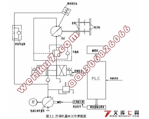
系统一般由三相交流异步电动机、电液比例变压泵、变量马达、换向阀和各类液压阀等部件组成,它的控制器采用三菱PLC。由于施工升降机上!下行工作原理基本相似,因此以上行工作原理为例介绍"施工升降机上行工作开始时,可编程控制器PLC接收到来自触摸屏的选层及上行控制指令,PLC输出上行控制信号使上行电磁阀YV1带电,电机启动接触器KMI通电,启动变量泵工作,油液进入马达,带动曳引轮旋转,从而施工升降机吊笼起动。
同时,PLC按照理想加速曲线输出相应的加速曲线信号经D/A模块后至例放大器,比例放大器为比例电磁铁提供特定的控制电流,从而控制变量泵的输出流量,进而控制吊笼的起动运行速度,当速度达到最大值时,吊笼以速度最大值稳定运行"在施工升降机运行过程中,PLC接收井道装置各信号,数据处理后将楼层当前位置!运行监控状态等信息通过触摸屏中及时显示,以便了解施工升降机的运行状态"当PLC接收到减速点信号时,PLC按照理想减速曲线模拟输出速度,比例电磁铁的输入电流也随着理想减速曲线减少,液压系统流量减少,从而吊笼运行速度不断下降"当施工升降机到站时,PLC输出控制信号使上行电磁阀YVI不带电,电动机启动接触器KMI失电,液压系统关闭,施工升降机停止运行。


目 录
摘 要 III
Abstract IV
目 录 V
1 绪论 1
1.1 升降机在国内外的发展现状 1
1.2 为何采用PLC控制系统的原因 2
1.2.1 PLC控制系统的发展和生产 2
1.2.2 PLC控制技术区别于其他控制技术 2
2 升降机的具体工作原理和其组成 5
2.1 升降机的基本工作原理 5
2.2 升降机的主要组成部分 6
3 升降机控制系统的硬件设计 8
3.2控制系统的主要性能 8
3.2.1 比例变量泵的介绍 8
3.2.2 可编程控制器和模块选择 9
3.3控制电路设计 12
3.3.1电路设计 12
3.3.2 系统回电路设计 13
3.3.3 输入输出回路设计 13
3.3.4 PLC的I/O存储地址分配 14
4 升降机控制系统软件设计 16
4.1 概述 16
4.1.1 PLC及运行原理 16
4.1.2 PLC运行软件 17
4.1.3 编程工具软件和编程语言 17
4.1.4 PLC软件的设计 17
4.2 控制系统的设计 18
4.2.1 楼层位置信号的发生和清除环节 19
4.2.2 选层指令登记、消除与显示 20
4.2.3停层信号的发生与消除 21
4.2.4 停车制动 21
4.2.5 启动加速与稳定运转 22
5 控制系统抗干扰设计 24
5.1电磁干扰类型和影响 24
5.2 PLC系统干扰来源 24
5.3 抗干扰措施 25
5.3.1 控制电源系统引发的干扰 25
5.3.2 控制输出端引发的干扰 25
5.3.3 安装和布线 25
5.3.4 正确选择接地点 26
6 结论和展望 27
致谢 28
参考文献 29
附录 30
|


