摩托车发动机相关零部件的设计(含cad零件图和装配图,工艺卡)(开题报告,进度检查表,外文翻译,中期报告,设计说明书17000字,CAD图纸7张)
摘 要
发动机是机器的“心脏”,它是机器最重要的部分,随着科学技术的飞快发展,国际之间关于发动机的竞争也也越来越激烈,所以对发动机的研究具有重要的科学意义。本文的设计方法采用常规手段与微机辅助相结合。
在设计中首先查阅中外资料,了解发动机的结构及工作原理,确定本文所设计的发动机结构。本文主要针对摩托车发动机的缸体、连杆、活塞等零部件进行设计。缸体的设计主要内容包括气缸体的结构设计、材料的选择和参数设计,缸体是发动机零部件中重要的零部件,所以在本文中还对缸体进行加工工艺规程进行设计从而确定加工工艺路线。连杆的设计的主要内容是连杆的结构、连杆承受的载荷和连杆的位移等。活塞设计的主要内容是活塞的材料的选择、主要参数和活塞的运动分析。
关键词:摩托车发动机;
Abstract
The engine is the "heart" of the machine, it is the most important part of the machine. With the fast development of science and technology, the competition is also more and more fierce among countries, so it has important scientific significance for engine research. The design method of this paper has combined conventional means and computer-aided.
In order to determine the design structure of engine, this paper has consulted the Chinese and foreign information and understood the structure and working principle of the engine. This paper focuses on the design and 3D modeling of motorcycle engine cylinder block, connecting rod, piston and other parts. The design of cylinder mainly includes cylinder block structural design, materials selection and parameter design, the cylinder is the important parts of the engine parts, so this article has completed the design of cylinder planning process in order to determine route. The design of connecting rod mainly includes the structure of the connecting rod, bear the load and connecting rod displacement. The design of piston mainly includes piston material selection, analysis of the main parameters and the movement of the piston. This paper also uses UG software to complete the three-dimensional modeling of cylinder, piston, connecting rod and assemble of parts. Then this paper has completed the conversion of parts of the three-dimensional to two-dimensional drawings and motion simulation analysis for assemble.
Key words: motorcycle engine; UG; three-dimensional modeling; motion simulation
本课题的主要内容
本文设计的主要内容有缸体、连杆、活塞的设计以及缸体的加工工艺规程的设计。对于缸体的设计主要是通过缸体的结构设计、材料的选择、参数设计来完成,连杆的设计主要是通过连杆的位移、结构来完成,活塞的设计主要是通过活塞的参数设计及运动分析来完成,缸体的加工工艺规程主要是通过制定工艺路线和切削用量来完成。


目 录
摘 要 III
ABSTRACT IV
目 录 V
1 绪论 1
1.1 本课题研究的科学意义 1
1.2 发动机的发展史及国内外的发展概况 1
1.3 本课题的主要内容 2
2 气缸体的设计 3
2.1 气缸体的结构设计 3
2.2 气缸体材料的选择 3
2.3 气缸体参数设计 4
2.3.1 气缸直径 4
2.3.2 气缸形状的设计 5
2.3.3 气缸工作容积、燃烧室容积和气缸总容积 5
2.3.4 压缩比 6
2.3.5 气缸工作内压力与气缸总推力 7
2.4 气缸盖 7
2.5 燃烧室 9
3 连杆的设计 11
3.1 连杆的组成 11
3.1.1 小头 12
3.1.2 杆身 12
3.1.3 大头 12
3.2 曲柄连杆比 12
3.3 连杆承受的载荷 12
3.4 连杆的角位移、角速度、角加速度 13
4 活塞的设计与运动分析 15
4.1 活塞的功用及工作条件 15
4.2 活塞的材料 16
4.3 活塞的主要参数 16
4.4 活塞的运动分析 16
4.4.1 活塞位移 16
4.4.2 活塞的速度 17
4.4.3 活塞的瞬时速度 18
4.4.4 活塞的最高速度 18
4.4.5 活塞的平均速度 19
4.4.6 活塞的加速度、最大加速度 19
5 基于UG软件的三维建模 21
5.1 UG软件介绍 21
5.2 UG软件的优势及主要功能 21
5.3 三维建模 23
5.3.1 缸体的三维建模 23
5.3.2 活塞的三维建模 25
5.4 零件的装配 26
5.4.1 装配的概述 26
5.4.2 活塞与活塞销的转配 26
6 运动仿真 28
6.1 运动仿真的简介 28
6.2 零件装配图的运动仿真 28
7 缸体的加工工艺规程设计 31
7.1 确定毛坯的制造形式 31
7.2 气缸体的加工工艺特点 31
7.3 基准的选择 31
7.4 制定工艺路线 31
7.5 加工余量及切削用量的确定 32
8 结论与展望 36
8.1 结论 36
8.2 不足之处及展望 36
致谢 37
参考文献 38
附 录 39
附 录
一、缸体加工主要工序的工艺卡片
二、零件图及装配图
1、缸体 A0 1张
2、活塞 A2 1张
3、气缸盖 A2 1张
4、曲柄 A3 1张
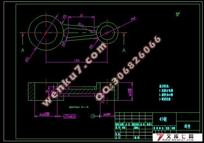
5、连杆 A3 1张
6、活塞销 A4 1张
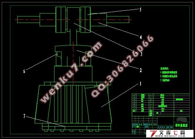
7、装配图 A2 1张
|


