机车轴承座自动上下料专用机构的设计(含CAD零件图装配图)(选题审核表,任务书,开题报告,外文翻译,论文说明书9000字,CAD图15张)
Special mechanism for automatic loading and unloading of locomotive bearing seat
摘要
本设计主题是一种用于机车轴承座自动装卸的特殊机制。工业水平日渐上升并不断提高,工业生产趋于自动化。,解放人力的同时又带来许多机遇,在这个阶段,自动化生产显然已经成为人类追求的目标,并且现在已经慢慢实现,出来了许多机器人,如汽车加工中的机械手,本次设计也是一类机械手机器人,主要作用于机车轴承座生产中实现工件的自动上下料,翻转等一系列的动作,在加工过程中实现自动化生产。
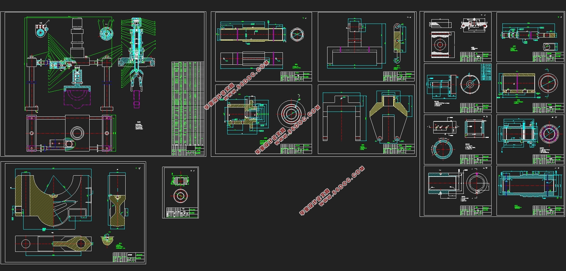
本次设计的过程中所要完成的任务很多,要绘制该机械手的总体装配图及部装图和非标零件图,同时还要整理所设计部分的计算说明书。
设计时,首先要选择机械手的驱动方式,这里我选择液压系统驱动,因为该机械手是4自由度的机械手,4个自由度分别为夹紧/松开,升降和回转。因此,夹紧液压缸,提升液压缸和旋转液压缸的设计。
所以该机械手不但满足这4个自由的动作,它还可以确保可靠抓取,平稳灵活的传送以及准确的定位。同时还要进行液压系统的简单设计,液压系统的优势非常明显,体积小,重量轻;高刚性,高精度和快速响应;驱动力大,适合直接驱动重物;速度范围宽,速度控制方式多样;自润滑,自冷却,寿命长;容易实现安全保护。
设计的目的是在满足要求的前提下尽可能的符合实际的工作情况和安全情况,在工作车间的工作状况会导致某些动作的危险,还要考虑到机械手的成本,所以要从结构设计和运动学分析上解决问题,以实现本次设计的最终要求。
关键词:自动上下料;机械手;液压系统。
Abstract
This design theme is a special mechanism for automatic loading and unloading of locomotive bearing seats. With the continuous improvement of industrial level, industrial production tends to be automated. At the same time, the liberation of manpower brings many opportunities. At this stage, automated production has obviously become the goal pursued by mankind, and has now been slowly realized. Many robots, such as robots in automobile processing, have come out. The manipulator robot is mainly used to realize the automatic loading and unloading and turning of the workpiece in the production of locomotive bearing seats, and to realize automatic production during the processing process.
There are many tasks to be completed in the design process. The general assembly drawing, part assembly drawing and non-standard part drawing of the manipulator must be drawn. At the same time, the calculation instructions of the designed part must be collated.
When designing, we must first select the driving method of the manipulator. Here I choose the hydraulic system to drive, because the manipulator is a 4 degree of freedom manipulator, and the 4 degrees of freedom are clamping / unclamping, lifting and rotating. Therefore, the design of clamping hydraulic cylinder, lifting hydraulic cylinder and rotating hydraulic cylinder.
Therefore, the manipulator not only satisfies these four free movements, it can also ensure reliable grasping, smooth and flexible transmission and accurate positioning. At the same time, a simple design of the hydraulic system is also required. The hydraulic system is a little obvious, small and light; large rigidity, high precision and fast response; large driving force, suitable for direct driving of heavy loads; wide speed range, speed control mode Diversity; self-lubrication, self-cooling and long life; easy to achieve safety protection.
The purpose of the design is to conform to the actual working conditions and safety conditions as much as possible on the premise of meeting the requirements. The working conditions in the workshop will cause certain actions to be dangerous. The cost of the manipulator must also be considered. Kinematics analysis to solve the problem to achieve the final requirements of this design.
Keywords: manipulator; automatic loading and unloading; hydraulic system.
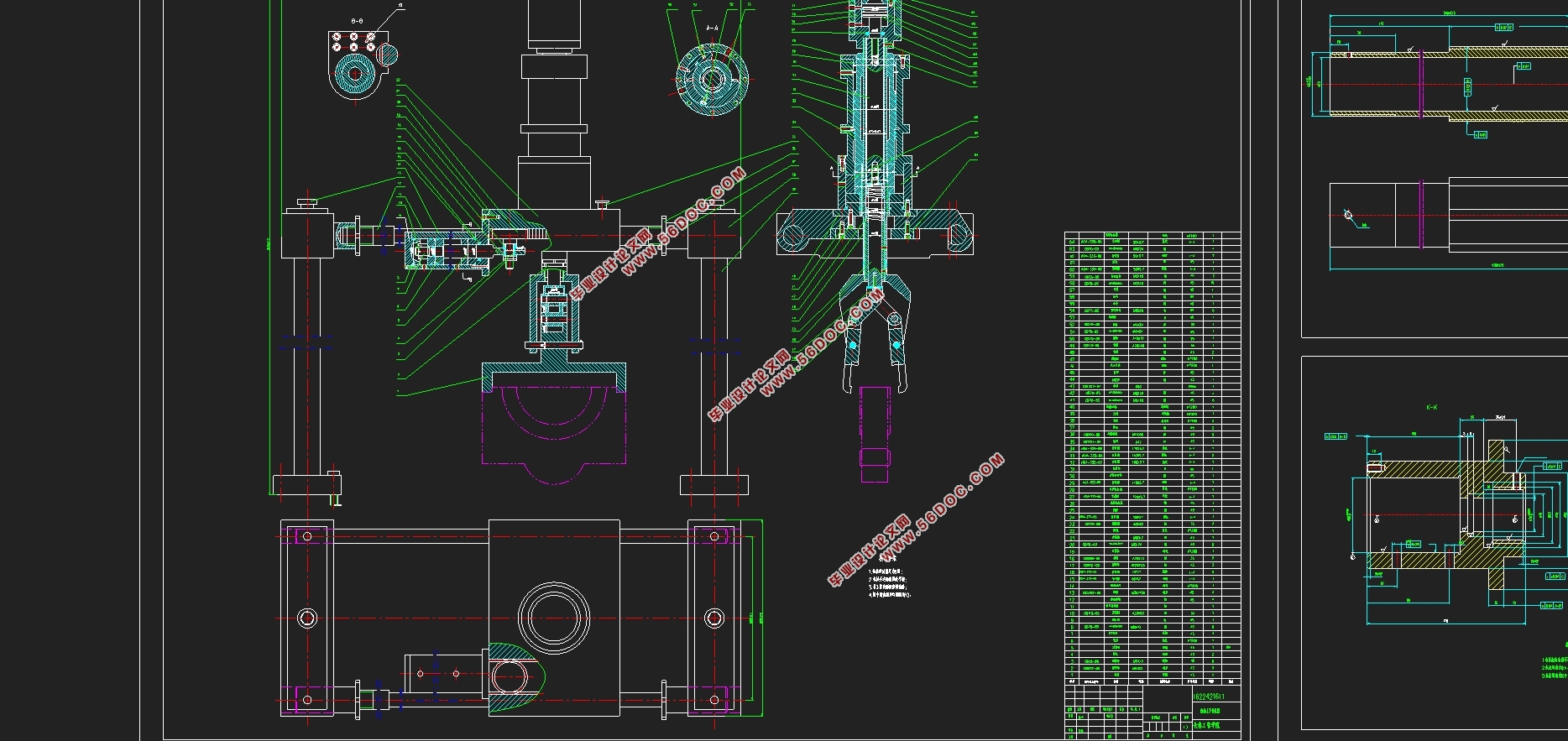
自动上下料的专用机构,用于机车轴承座生产线,夹紧工件后并将工件一定高度的提升,在将其旋转和移动位置。
其主要技术指标如下:
1. 工件重量约为75Kg;
2. 工件最大尺寸:440mm×92mm×290mm(有关详细信息,请参见零件图);
3. 最大工作范围:最大起升高度70mm,最大转弯角度90°,最大水平移动距离400mm;
4. 机械手的自由度数:4个自由度分别为夹紧或松开,升降,移动和回转。
5.装料高度:1100mm;
6.性能要求:可靠灵活的夹紧,稳定的释放和可靠的定位
此处设计使用圆柱坐标式机械手。夹爪的夹或松,手臂的上升和降落,纵向的回转和移位。
根据实际选择,液压传动处理器满足了我们的要求:其主要优点是:可以获得更大的生产能力,更小的传动速度,响应速度,并且易于控制输出功率和运动速度,并且可以实现更高的定位精度 。 通过夹紧液压缸,抬起液压缸,移动液压缸并旋转液压缸来控制紧固,拆卸,提升,向前和向后旋转。

目录
摘要 1
绪论 4
1. 课题论证 4
1.1机车轴承座自动上下料专用机构结构设计研究的目的与意义 4
1.2文献综述 4
1.2.1国外发展现状 4
1.2.2国内发展现状 4
第1章 自动上下料机构的设计 6
第2章 机械手总体设计 7
2.1 手臂设计 7
2.1.1 夹紧液压缸的计算 7
2.1.2 升降液压缸计算 8
2.1.3 回转液压缸计算 10
2.2 机身其他部位计算 11
2.2.1 移动缸计算 11
2.2.2 齿轮轴计算 13
2.2.3 滑板计算: 15
2.2.4导轨计算: 17
2.3 机械手手部计算 19
2.3.1 手部选型 19
2.3.2 计算手指夹紧力 19
2.2.3 计算手指驱动力 19
2.3.4 手部结构强度校核 20
第3章 液压传动系统简单说明 23
3.1本次设计液压系统组成: 23
3.2 液压缸结构设计: 23
3.3设计参数 24
3.3.1 确定机械手的动作顺序 24
3.3.2 主要设计参数确定 25
3.4 辅助设备的选择 25
3.4.1油管及接头配件 25
3.4.2 机油滤清器 25
3.4.3存油的油箱 26
结束语 26
参考文献与附录 27
|