三拐曲轴加工工艺及专用夹具设计(含CAD零件装配图,CREO三维图,工序卡)(任务书,论文说明书18000字,CAD图纸4张,CREO三维图,工序卡,实习调研报告)
摘 要
曲轴是很多机械设备的重要运动机构之一。它将活塞的往复直线运动变成旋转运动,将作用在活塞的气体压力变成扭矩,使机械和发动机各辅助系统进行工作。在曲轴行业飞速发展的今天,如何提高曲轴的生产能力和生产质量也成为了重中之重。这次设计的内容主要有,根据被加工曲轴的技术要求,进行工艺规程设计,运用夹具设计的基本原理和方法,拟定夹具设计方案,完成夹具结构设计。而这次设计完成的主要工作有:了解零件的结构特点和技术要求,并根据特点和要求绘制产品零件图;对零件进行结构分析和工艺分析;确定毛坯的种类及制造方法;拟定零件的机械加工工艺过程,选择各工序的加工设备和工艺设备,确定各工序的加工余量和工序尺寸,计算各工序的切削用量和工时定额;填写工艺卡片;设计指定工序的专用夹具,绘制装配总图和主要零件图;绘制三维装配建模图以及零件建模图;撰写毕业设计设计说明书。通过这次设计明显可以看出,合理的工艺编排和适当的加工参数能有效提高曲轴的制造能力。
关键词:曲轴加工;加工工艺;曲轴车削专用夹具;车床夹具设计
Abstract
Crankshaft is one of the most important movement mechanisms of many mechanical equipment. It turns the reciprocating straight motion of the piston into a rotating motion, which changes the gas pressure of the piston into torque, which is used for mechanical and engine auxiliary systems to work. With the rapid development of crankshaft industry, how to improve the production capacity and quality of crankshaft has become the top priority. The main contents of this design are, according to the technical requirements of the processed crankshaft, the design of process regulations is carried out, the basic principles and methods of fixture design are used, the fixture design scheme is drawn up, and the fixture structure is completed. The main work in this design is understand the structural features and technical requirements of the parts, according the characteristics and requirements to draw the product parts drawing, analyze the parts and the process, determine the types and manufacturing methods of the blanks, draw up the process for the machining of the parts, and select the processing equipment and work of each process art equipment, determine the processing allowance and process size of each process, calculate the cutting amount and time quota of each process; fill in the process card; design the special fixture for the specified process; draw the assembly general drawing and the main part drawing; draw the 3D assembly modeling drawing and the part modeling drawing; write the graduation design instruction manual. Through this design, it can be clearly seen that reasonable process arrangement and appropriate machining parameters can effectively improve the manufacturing capacity of crankshaft.
Keywords: Crankshaft processing; processing technology; crankshaft turning fixture; lathe fixture design
题目所给定的零件是三拐曲轴,它位于发动机连杆处,曲轴产生旋转运动,带动连杆使活塞产生往复运动,并将旋转运动转化为直线运动,它在工作过程中将承受周期性的复杂的交变载荷。其主要作用是传递转矩,使连杆获得所需的动力。
零件的工艺分析
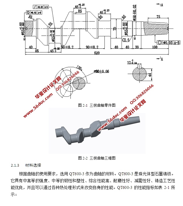
由图2-1可知,它的外表面上有多个平面需要进行加工,此外各表面上还需加工一系列螺纹、孔和键槽。因此可将其分为两组加工表面,它们相互间有一定的位置要求。曲轴精度要求比较高,所以工作表面的粗糙度与其他表面的粗糙度不一样。为加工三拐径,应制作专用工装,其要求为,能够均分三等份(曲轴三拐径偏心距为30±0.02mm),并要保持回转平衡[7]。现分析如下:
零件图样分析
l)"∅55mm两轴径同轴度公差为∅0.03mm" 。
2)"1:20锥度部分对A-B轴心线同轴度公差为∅0.03mm" 。
3)"三个拐径分别对A-B轴心线平行度公差为∅0.03mm" 。
4)"热处理,人工时效处理227~270HBW" 。
5)"三拐曲轴材料为QT600-3" 。
6)"三个拐径的粗糙度为Ra0.8。"
7)"∅55mm两轴径粗糙度为Ra0.8。"
8)"∅70mm外圆的粗糙度为Ra0.8。"
9)"∅55mm外圆的粗糙度为Ra0.8。"
10)其余表面是通过铸造得到的粗糙度。

目 录
摘 要 I
Abstract II
目 录 III
第1章 绪论 1
1.1 课题所涉及技术领域的基本情况 1
1.1.1 机械制造技术的发展 1
1.1.2 夹具行业的发展 1
1.1.3 制造技术的发展趋势 2
1.2 曲轴零件的特点及其加工方法 2
1.3 设计课题要达到的设计目的 2
第2章 可行性分析 4
2.1 零件分析 4
2.1.1 零件的工艺分析 4
2.1.2 零件图样分析 4
2.1.3 材料选择 5
2.2 毛坯的确定 6
2.2.1 确定毛坯的制造形式 6
2.2.2 铸造的加工余量及尺寸公差的确定 6
2.3 三种夹具方案设计 7
2.3.1 方案一夹具方案 7
2.3.2 方案二夹具方案 8
2.3.3 方案三夹具方案 9
2.4 加工工艺方案及可行性论证 9
2.4.1 初设三种工序方案 9
2.4.2 加工工艺方案一可行性论证评价 14
2.4.3 加工工艺方案二可行性论证评价 14
2.4.4 加工工艺方案三可行性论证评价 14
2.5 夹具方案可行性分析 14
2.5.1 技术方面 14
2.5.2 制造方面 15
2.5.3 知识储备 15
2.5.4 经济性方面 15
2.5.5 结论 15
第3章 工艺规程设计计算 17
3.1 三拐曲轴设计计算 17
3.1.1 基面的选择 17
3.1.2 粗基准选择 17
3.1.3 精基准的选择 17
3.1.4 加工工序的计算 17
3.2 夹具设计计算 29
3.2.1 问题的提出 29
3.2.2 定位基准的选择 29
3.2.3 定位元件的设计 29
3.2.4 切削力及夹紧力计算 29
3.2.5 定位误差分析 30
3.2.6 配重质量计算 31
3.3 绿色制造 32
第4章 产品使用与维护 33
4.1 夹具定位和夹紧 33
4.2 夹具的安装 33
4.3 夹具的使用过程 33
第5章 毕业设计特色专题 34
5.1 建模方法 34
5.2 零件建模 34
5.2.1 分度盘建模 34
5.2.2 回转盘建模 35
5.2.3 V型块建模 35
5.2.4 弧形压板建模 35
5.2.5 端盖建模 36
5.3 装配仿真 36
结 论 38
参考文献 39
致 谢 41
|


