Orcad在电子线路实验中的应用
来源:wenku7.com 资料编号:WK73474 资料等级:★★★★★ %E8%B5%84%E6%96%99%E7%BC%96%E5%8F%B7%EF%BC%9AWK73474
以下是资料介绍,如需要完整的请充值下载。
1.无需注册登录,支付后按照提示操作即可获取该资料.
2.资料以网页介绍的为准,下载后不会有水印.资料仅供学习参考之用. 密 保 惠 帮助
资料介绍
摘要
实验利用Orcad中的Capture进行电路图的设计,PSpice对电路进行编程及模拟仿真,并对电路的功能进行验证。对传统数字电路实验中的逻辑电路、时序电路、以及对称CMOS电路进行特性分析。本文所讨论的实验手段,相较于传统手段进行实验具有省时、耗材小,集成度高,结果精准的特点,且电路图绘制完成后可直接进行电路仿真,并且可以随时分析观察Probe的仿真结果,所以是学生进行实验时的良好辅助验证方法。
关键词:验证,分析,逻辑电路,时序电路,CMOS电路,模拟仿真。
THE APPLICATION OF CAD IN ELECTRONIC CIRCUIT EXPERIMENT
Absract:
The experiment makes use of the design that Capture in the Orcad proceed verification method. electric circuit diagram, the PSpice proceeds to weave to the electric circuit distance and emulations imitate true, its and proceed the verification to the function of the electric circuit.The traditional electric circuit experiment of the logarithms word electric circuit, logic electric circuit, cycle time electric circuit, and the CMOS electric circuit proceeds the characteristic analysis.This text an experiment for discussing means, because of its mutually than start experiment to have the material of save time, consume in the traditional means small, gather the degree is high, precise characteristics in result, and the electric circuit diagram draw to can proceed directly after completing the electric circuit imitates true, and can analyze at any time the observational Probe imitate true result, so is a student to start experiment good assistance
Keywords: Verification, analysis, logic electric circuit, cycle time electric circuit, the electric circuit of CMOS, simulate.
研究目标与主要内容
电子线路CAD实验,基于ORCAD软件
目标:对传统数字电路实验中的逻辑电路、时序电路、以及对称CMOS电路进行特性分析。
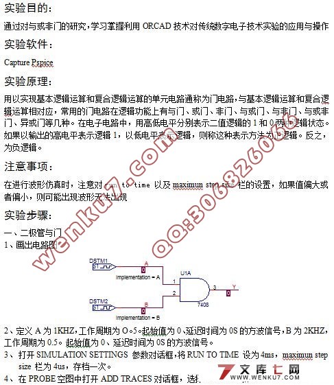
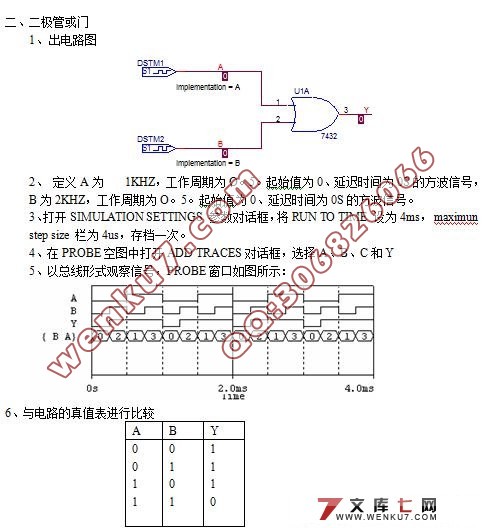
主要内容:1.编辑原理图 ,2.仿真波形,与传统实验仿真结果进行比较。
拟采取的研究方法、研究手段及技术路线、实验方案等
采用Orcad软件对传统实验中的时序电路与组合逻辑电路,利用CMOS对称技术制成的电路进行研究与仿真,同时与传统手段实施的实验进行比较,研究Orcad在电子技术实验方面的先进性。


摘要 ………………………………………………………….
Abstract ……………………………………………………..
引言 ………………………………………………………….
实验一 与或非门电路 …………………………………………..
实验二 BCD—七段显示译码器 ………………………………..
实验三 同步二进制加法计数器 ………………………………...
实验四 集成3线-8线译码器 ………………………………...
实验五 组合逻辑电路仿真 ……………………………………..
实验六 时序逻辑电路仿真 ……………………………………
实验七 非周期性数字输入信号源 ……………………………….
实验八 电流源与电流镜 …………………………….……….…
实验九 二值检正运算电路和检负运算电路 ……………………. 23
实验十 三值跟随器 …………………………..……………….. 26
|


