激光测距仪系统设计(机械图,电路图,c语言程序)
来源:wenku7.com 资料编号:WK73401 资料等级:★★★★★ %E8%B5%84%E6%96%99%E7%BC%96%E5%8F%B7%EF%BC%9AWK73401
以下是资料介绍,如需要完整的请充值下载。
1.无需注册登录,支付后按照提示操作即可获取该资料.
2.资料以网页介绍的为准,下载后不会有水印.资料仅供学习参考之用. 密 保 惠 帮助
资料介绍
激光测距仪系统设计(机械图,电路图,c语言程序)(毕业论文22000字,cad图纸,答辩ppt)
摘 要
本次激光测距仪系统设计采用的是相位式测距法,相位激光测距又称调幅连续波激光测距通常是基于对目标回波相位的探测,在诸如军事、航空、工业和体育等领域已经取得广泛的应用。相位激光测距仪的发展趋势是小型化、高可靠性、便于与其他仪器集成。
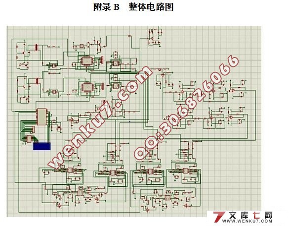
本文介绍了相位式激光测距仪的测距原理,提出了测距系统的具体设计方案。 设计围绕接收和发射系统的性能开展,主要包括了锁相环、分频器、信号整形与放大电路、弱信号检测滤波与放大电路、混频器、鉴相测相器、信号处理与显示电路、单片机 89C51 的软硬件设计和C语言软件编程等问题。利用Proteus软件对系统电路进行绘制以及利用CAD设计了系统机械的结构。
关键词: 激光测距;相位;锁相环;混频器;分频器;单片机
System Design of a Laser Range Finder
ABSTRACT
The phase-ranging method is adopted in the system design of the laser range finder. It is also known as amplitude modulation of continuous wave laser ranging and is usually based on the detection of the phase of the target echo, has been widely used in many fields such as military, aerospace, industrial and sports etc.
This thesis first introduces ranging principle of phase-shift laser range finder and proposes the concrete design scheme. Design is carried out around the performance of the receive and transmit systems, which includes the designs of phase-locked loop, frequency divider, signal shaping && amplifying circuit, weak signal detection filter && amplifier, frequency mixer, phase discriminator && detector, signal processing and display circuit and the hardware && software of the 89C51 microcontroller, and C language software programming. Proteus software is used to draw the circuits in the system drawing and CAD is applied to design the mechanical structure of the system.
Keywords: Laser ranging; Phase; Phase locked loop; Frequency mixer; Frequency divider; Single chip microcomputer
创新思路
本次设计将要完成的主要创新点如下:
1.根据相位式激光测距原理,采用测尺组合频率和差频测相的方法完成测量,提高测量精度。
2. 提高整体的稳定性,降低消耗。
3. 采用模块形式提高电路的分辨率,克服电路系统中各个频率的干扰。
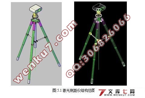
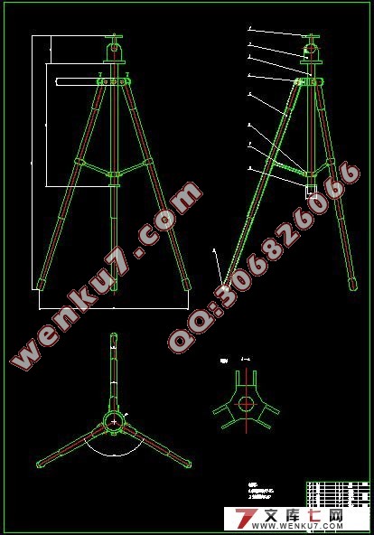
4. 优化系统结构,采用支架式结构避免测量时系统晃动现象的产生。
本激光测距仪的基本设计和参数指标如下:
1、发射电路:由15MHz的有源晶振(主振)通过分频产生1.5MHz的晶振(主振2),两频率的晶振同时驱动半导体激光器LD发出激光束。
2、接收部分:光电转化器把反射回来的两束晶振频率通过放大器将其放大。
3、锁相环:15MHz和1.5MHz的晶振分别通过锁相环产生15.1MHz和1.51MHz的正弦信号分别作为本振1和本振2。
4、混频器:分别把主振信号和本振信号、主振与回波信号、本振与回波信号混合相减得到对应的频率差并将其放大。
5、缓冲整形:正弦波变方波,模拟信号转化成数字信号。
6、CPLD:测量发射波与回波的相位差。
7、单片机:处理数据与控制显示。
8、LED数码管:显示测量数据。
9、用运算放大器设计探测接收部分滤波器和放大器。
10、用于测相的差频信号频率为 10KHz,相位测量精度能达到千分之一以上。
11、理论测量范围为100m,测量精度为1cm。
12、用双栅场效应管作混频器,用 LC 振荡器作锁相环的压控振荡器,采用模拟锁相环。
13、本系统的特点是高精度、快速、实时显示、操作简单,数字与模拟结合。
|
