基于电流环的信号变送装置的设计(附电路原理图)
来源:wenku7.com 资料编号:WK716624 资料等级:★★★★★ %E8%B5%84%E6%96%99%E7%BC%96%E5%8F%B7%EF%BC%9AWK716624
以下是资料介绍,如需要完整的请充值下载。
1.无需注册登录,支付后按照提示操作即可获取该资料.
2.资料以网页介绍的为准,下载后不会有水印.资料仅供学习参考之用. 密 保 惠 帮助
资料介绍
基于电流环的信号变送装置的设计(附电路原理图)(论文12000字)
摘要
变送器功能是将传感器的非电能转换成电信号并远程测量和控制。电流变送器将测得的信号转换成线性关系并与测量的信号完全隔离的电流,通常为4 mA -20mA。转换后的信号以电流形式传输,大大提高了抗干扰能力。本系统以电流环为核心,设计一个将电阻量转换为与之成良好线性关系、完全隔离的电流量。系统主要由微控制器、激励电流源、差分电路、DAC、LCD显示、光耦隔离、电流环、电源隔离等硬件构成。激励电流源将可变电阻转换为电压信号,并进行差分输入微控制器的内部ADC采样处理。微控制器根据被测电阻值换算对应的电流环的控制电压,并通过SPI总线驱动AD5660产生该电压信号,使电流环输出4-20mA的电流。采用集成隔离电源使电流环的驱动电源与其它电路隔离,并采用光耦芯片使AD5660产生的电压量与数字总线隔离,提高精度。实验测试表明,系统能准确测量电阻值,并根据电阻值输出对应的隔离电流信号。电流输出误差为0.2%。
关键词:电流环,DAC,隔离,微控微器
Abstract
The function of the transmitter is to convert the non-electrical energy of the sensor into an electrical signal and measure and control it remotely. The current transducer converts the measured signal into a linear relationship and is completely isolated from the measured signal, typically 4 mA - 20 mA. The converted signal is transmitted in the form of current, which greatly improves the anti-interference ability. This system takes the current loop as the core, and designs a current that converts the resistance into a well linear relationship with it. The system is mainly composed of hardware such as a microcontroller, an excitation current source, a differential circuit, a DAC, an LCD display, an optocoupler isolation, a current loop, and a power supply isolation. The excitation current source converts the variable resistor to a voltage signal and performs internal ADC sampling of the differential input microcontroller. The microcontroller converts the control voltage of the corresponding current loop according to the measured resistance value, and drives the AD5660 through the SPI bus to generate the voltage signal so that the current loop outputs a 4-20 mA current. The use of an integrated isolated power supply isolates the current loop drive power from other circuits and uses an optocoupler chip to isolate the voltage generated by the AD5660 from the digital bus, improving accuracy. Experimental tests show that the system can accurately measure the resistance value and output the corresponding isolated current signal according to the resistance value. Current output error is 0.2%.
Keywords: Current loop, DAC, Isolation, Microcontroller

目 录
摘要 3
Abstract 4
1 引言 5
2 总体方案设计 6
2.1 总体设计思路 6
2.2 各模块电路方案的确定与论证 6
2.2.1 恒流源电路 6
2.2.2 电流环电路 7
2.2.3 数/模转换器的选择 8
2.2.4 电压线性转换部分方案的选择 8
2.2.5 单片机的选择 9
2.2.6 显示模块的选择 9
2.3 电路总体设计方案 9
3 硬件电路设计 10
3.1 单片机最小系统的设计 10
3.1.1 复位电路设计 12
3.1.2 晶振电路设计 12
3.1.3 电源滤波电路 13
3.1.4 单片机最小系统电路 13
3.2 恒流源电路设计 14
3.3 可变电阻电路与差分电路的设计 14
3.4 数模转换电路设计 15
3.5 电流环驱动电源 16
3.6 电流转换电路设计 16
3.7 显示电路设计 17
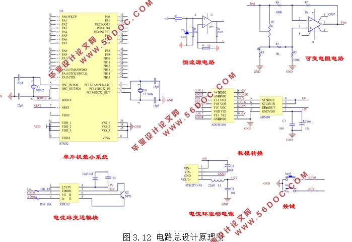
3.8 电路总设计原理图 18
4 软件流程图分析 19
4.1 软件设计环境介绍 19
4.2 主程序流程图 19
4.3 显示模块驱动流程 20
4.4 按键模块流程 21
4.5 DAC配置过程 22
5 实验测试 23
5.1 系统功能 23
5.2 实验测试 23
6 总结 24
参考文献: 26
致谢 27
|


