400Hz中频电源的设计(附电路图)
来源:wenku7.com 资料编号:WK713907 资料等级:★★★★★ %E8%B5%84%E6%96%99%E7%BC%96%E5%8F%B7%EF%BC%9AWK713907
以下是资料介绍,如需要完整的请充值下载。
1.无需注册登录,支付后按照提示操作即可获取该资料.
2.资料以网页介绍的为准,下载后不会有水印.资料仅供学习参考之用. 密 保 惠 帮助
资料介绍
400Hz中频电源的设计(附电路图)(任务书,开题报告,中期报告,外文翻译,论文7000字)
摘 要:随着科学技术的发展以及提高我国国防能力的需要,对军事设施的技术改造已被列为军事技术改造中的重点。中频电源指输出频率为400Hz的电源,它可以为动力系统及导航与武备系统供电。传统的400Hz中频电源体积大,输出波形不稳定。本文所设计的400Hz中频电源采用了稳定的石英晶体振荡回路,通过分频电路、积分电路、放大电路和检波电路及单片机系统,控制其最后的输出电压,实现了电压的稳定输出,具有体积小、功率大和波形无失真等优点,有着广泛的用途和良好的发展前景。
关键词:中频电源 单片机 正弦波
The Design of the 400Hz Intermediate Frequency Power Supply
Abstract: With the development of technology and the increasing requirements of national defense, the technical innovation on military establishment has become the key part in military affairs. The power supply of intermediate frequency whose output frequency is 400Hz can provide power for the system of motion, navigation and weapon equipments. The wave output from traditional power supply of intermediate frequency is unsteady. The design in this text adopt the oscillating circuit based on quartz crystal oscillator, and the hardware made up of the divided frequency circuit, integral circuit, amplifying circuit, demodulation circuit and SCM(Single Chip Microcomputer)system can control the output voltage at the end. The circuit realizes the steady output of voltage, and the characteristics such as small volume, high power and no distortion of wave make it widely used and have a bright future.
Keywords: The power supply of intermediate frequency SCM Sine Wave
(1) 实现输出频率为稳定的400Hz正弦波。
(2) 输出波形没有明显失真。
(3) 输出电压为25V~65V连续可调(有效值)。
400Hz中频电源的硬件原理与设计
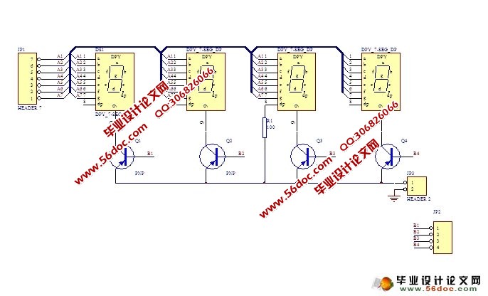
4MHz信号基准电源,通过分频电路进行分频得到400Hz的信号,经过积分电路将方波转化为正弦波,为提高电压的幅值还要经过放大电路进行放大,再通过升压变压器使最后的输出电压的有效值在25V~65V之间。通过检波电路得到直流电压,AD采集首先将模拟信号转变成数字信号后,再将采集到的电压值送到单片机中,最后通过单片机送到数码管显示电压,为保证放大电路中TDA7294的正常工作,单片机控制系统还通过稳压电路为其提供电压。

目 录
1 引言……………………………………………………………………………………1
2设计要求 ………………………………………………………………………………1
3 400Hz中频电源的硬件原理与设计 ………………………………………………………1
3.1振荡电路…………………………………………………………………………………2
3.2分频电路…………………………………………………………………………………2
3.3 积分电路 ………………………………………………………………………………4
3.4 放大电路 ………………………………………………………………………………6
4.2控制电路的原理与设计方案 …………………………………………………………9
5测试结果………………………………………………………………………………11
6结论……………………………………………………………………………………12
参考文献…………………………………………………………………………………13
致谢………………………………………………………………………………………14
附录 系统电路图………………………………………………………………………… 14
英文资料及中文翻译………………………………………………………………………15
|


