基于单片机的无线可视门铃设计
来源:wenku7.com 资料编号:WK717258 资料等级:★★★★★ %E8%B5%84%E6%96%99%E7%BC%96%E5%8F%B7%EF%BC%9AWK717258
以下是资料介绍,如需要完整的请充值下载。
1.无需注册登录,支付后按照提示操作即可获取该资料.
2.资料以网页介绍的为准,下载后不会有水印.资料仅供学习参考之用. 密 保 惠 帮助
资料介绍
基于单片机的无线可视门铃设计(论文10000字)
摘要
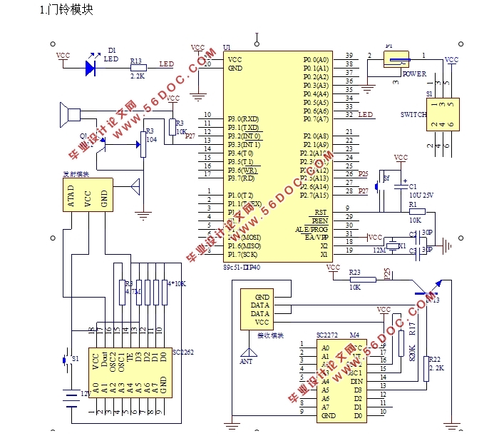
现在,我们国家的住宅水平已经进入一个崭新的时代,住宅需求从追求单一生存空间的数量型需要向追求数量,质量,功能,服务等多重需求转变。本文是对无线可视门铃进行了设计,采用单片机作为控制芯片,摄像头和信号发射模块通过WIFI模块传送数据给单片机,经过单片机的计算处理后发送信号给喇叭和继电器,实现门铃的功能。本设计以门铃模块和可视模块构成,门铃模块包括信号发射电路,信号接收电路和音乐播放电路。访客按下门铃后,信号发射电路产生信号后将信号发射出去并由信号接收电路接收经单片机处理后控制音乐播放电路工作。可视模块包括计算机控制软件和继电器电路,主人听到门铃后可以在计算机控制软件上观察门外情况通过按键来控制继电器的闭合。
关键词:无线可视门铃 单片机 继电器
Abstract
At present,At present, China's residential development has entered a new period of development, residential demand from quantity demand of the pursuit of simple living space to the pursuit of quantity, quality, function, service over multiple needs.This article is the design of the wireless video doorbell,Using single chip microcomputer as control chip,The camera and the signal transmitting module transmits the data to the single chip microcomputer through the WIFI module,After the calculation of the single-chip microcomputer to send a signal to the speaker and relay, to achieve the function of the door bell。This design is composed of the door bell module and the visual module,The doorbell module comprises a signal transmitting circuit, a signal receiving circuit and a music playing circuit.After the visitor presses the door bell, the signal transmitting circuit generates a signal, and the signal is transmitted out and received by the signal receiving circuit to control the music playing circuit after the single chip computer is processed.The visual module comprises a computer control software and a relay circuit, and the host can observe the situation on the computer control software to control the closing of the relay on the computer control software after the master hears the doorbell.
Keyword:Wireless visual doorbell;MCU;Relay

摘要 I
Abstract II
第一章绪论 3
1.1课题研究的背景和意义 3
1.1.1概述 3
1.1.2发展前景分析 3
1.1.3可视门铃系统的发展现状及特点 4
1.2课题研究的主要内容 4
第二章可视门铃系统的主要功能和方案设计 6
2.1可视门铃系统的主要功能 6
2.2可视门铃系统的整体方案 6
2.2.1设计原理 6
2.2.2系统框图 7
2.3不同模块的方案设计 8
2.3.1门铃模块 8
2.3.2可视模块 9
2.4小结 10
第三章硬件电路设计 11
3.1门铃模块电路 11
3.1.1 AT89C52单片机最小系统电路 11
3.1.2发射模块电路图 13
3.1.3接收模块电路图 14
3.2可视模块电路 15
3.2.1AT89C2051单片机最小系统电路.........................................................................13
3.2.2继电器模块 17
3.3小结 17
第四章无线可视门铃的软件设计 18
4.1软件设计思路 18
4.2门铃模块和可视模块的程序设计 18
4.2.1门铃模块 19
4.2.2可视模块 22
4.3计算机控制软件 24
4.3.1界面布局 24
4.3.2WIFI连接与数据传输 25
4.4小结 25
第五章仿真与调试 26
5.1软件仿真 26
5.2硬件调试 27
5.3结果简述 29
5.4问题反思 29
5.5小结 29
结语 30
参考文献 31
附录一电路原理图 33
附录二硬件实物图 35
|


