基于单片机的GPS和电罗经数据模拟器设计(附程序清单)
来源:wenku7.com 资料编号:WK717115 资料等级:★★★★★ %E8%B5%84%E6%96%99%E7%BC%96%E5%8F%B7%EF%BC%9AWK717115
以下是资料介绍,如需要完整的请充值下载。
1.无需注册登录,支付后按照提示操作即可获取该资料.
2.资料以网页介绍的为准,下载后不会有水印.资料仅供学习参考之用. 密 保 惠 帮助
资料介绍
基于单片机的GPS和电罗经数据模拟器设计(附程序清单)(任务书,开题报告,外文翻译,论文14000字,程序清单)
摘要
一直以来,GPS和电罗经就是船舶运行所必备的仪器。GPS可以显示船舶的动态位置,电罗经则用来指示真北基准,提供船舶的航向信号,故其对于船舶的航向和位置精准控制起着非常重要的作用。对此,本文设计了一种基于单片机的GPS和电罗经数据模拟器来实时采集船舶的运行情况,系统采用以ARM Cortex-M3处理器为核心的STM32F103VET6单片机作为主控制器,首先利用其搭载的串口对GPS和电罗经的数据进行采集,并将其存储到SD卡中,然后利用WIFI模块配置软件对UART-ETH-WIFI模块进行配置,开启WIFI,最后对SD卡中存储的数据进行读取,将得到的数据通过WIFI上传到地面数据采集系统,进行实时显示。设计出的系统可以实现题目中的所有要求。
关键字:GPS;电罗经;数据模拟器;STM32;WIFI
Abstract
From the past to the present,GPS and electric gyrocompass is necessary to run the ship navigation equipment .GPS can display the dynamic position of the ship, and the electric compass is used to indicate the true benchmark to provide ship,s heading signal. It is very important for precise control of the ship,s course and position. Therefore, the design of the proposed research and development of a microcontroller based GPS and electric gyrocompass data simulator to realize real-time acquisition data. The system uses Cortex-M3 ARM processor as the core of the STM32F103VET6 microcontroller as the main controller. Firstly, collect data of GPS and electric gyrocompass by A/D interface, and store it in SD card. Then, use the serial port to configure the UART-ETH-WIFI module,and open WIFI. Finally, read data stored in SD card, and upload the obtained data to the ground data acquisition system through WIFI to real-time display. The system can be designed to achieve all the requirements of the title.
Key words:GPS;Electric gyrocompass;Data simulator;STM32;WIFI


目录
第1章 绪论 1
1.1 课题背景 1
1.2 国内外研究现状 1
1.2.1 GPS和电罗经研究现状 1
1.2.2 单片机研究现状 2
1.3 研究内容 2
1.4 论文结构 3
第2章 数据模拟器主要技术 4
2.1 GPS模块 4
2.2 电罗经模块 4
2.3 主控制器选择 4
2.4 串口通信 5
2.5 SD卡驱动 5
2.6 直接存储器读取(DMA) 6
2.7 WIFI模块 6
第3章 数据模拟器硬件设计 7
3.1 系统总体设计要求分析 7
3.2 系统总体方案介绍 7
3.3 数据采集模块设计 8
3.4 数据存储模块设计 8
3.5 无线通信模块 8
第4章 数据模拟器软件设计 11
4.1 软件设计思路 11
4.2 STM32工程的建立 12
4.2.1 开发工具的配置 12
4.2.2 工程模板的建立 12
4.2.3 配置J-LINK硬件调试及程序下载 14
4.3 数据采集实现 15
4.4 数据存储实现 15
4.5 无线通信实现 16
4.5.1 硬件测试 16
4.5.2 串口AT指令模式 19
4.5.3 AT指令 20
4.5.4 WiFi AP模式配置 22
第5章 数据模拟器测试结果 25
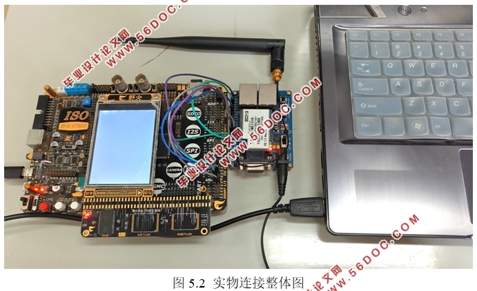
5.1 实物连接 25
5.2 数据采集 27
5.2.1 GPS数据 27
5.2.2 电罗经数据 27
5.3 地面数据采集系统数据 27
第6章 总结与展望 29
参考文献 30
致谢 31
|


