利用STM32单片机设计数字示波器设计(附PCB图,电路原理图,实物图)(任务书,开题报告,论文9000字)
摘 要
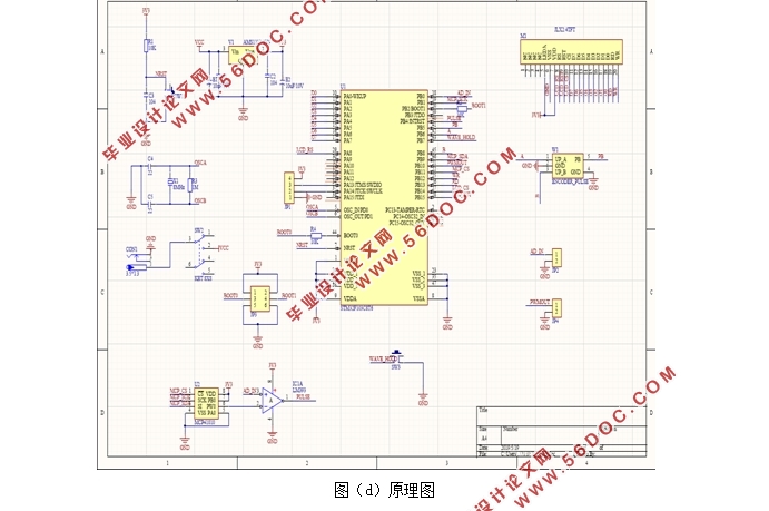
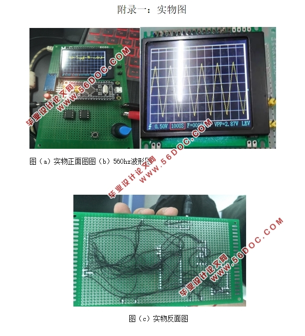
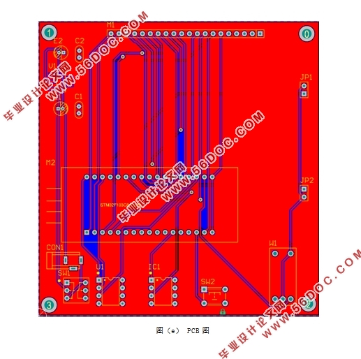
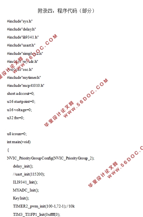
本论文设计了一款以STM32F103C8T6芯片为核心的单片机示波器,其主要由硬件电路和软件程序两大模块组成。硬件模块主要包括TFTLCD液晶显示屏、独立按键、ISP串口下载程序接口、时钟系统、电源系统等。软件模块主要包括A/D采样、液晶显示、中断定时以及一些必要的数据处理。本设计基于MDK5环境,下载程序到STM32芯片中,其可测量的带宽是0-3000Hz,测量的幅度是0-3.3V。经过多次测试与比较,本设计在实验过程中实现了波形的放大与缩小,以及低频波形的测量,从而达到预期目标。
相较于传统示波器,本设计的优点在于制作成本低廉,便于携带,能够测试一些小型电路,对于从事电子行业的工作者或者电路设计爱好者在电路制作和产品检测中,有着重要意义。
关键词:STM32数字示波器AD转换TFT液晶显示屏
Designing Digital Oscilloscopes with STM32 Microcontrollers
Abstract
This paper designs a SCM oscilloscope with STM32F103C8T6 chip as the core, which mainly consists of two modules: hardware circuit and software program. The hardware module mainly includes TFTLCD LCD screen, independent keys, ISP serial port download program interface, clock system, power supply system and so on. The software module mainly includes A/D sampling, LCD display, interrupt timing and some necessary data processing. This design is based on MDK5 environment, download the program to STM32 chip, its measurable bandwidth is 0-3000Hz, the measured range is 0-3.3V. After many tests and comparisons, the design achieves the amplification and reduction of waveform and the measurement of low frequency waveform in the experimental process, so as to achieve the desired goal.
Compared with the traditional oscilloscope, this design has the advantages of low cost, easy to carry, and can test some small circuits. It is of great significance for the workers engaged in electronic industry or circuit design enthusiasts in circuit making and product testing.
Keywords:STM32;Digitaloscilloscope;ADconversion;TFT liquid crystal display


目录
摘 要 I
Abstract II
第一章绪论 1
1.1设计背景 1
1.2设计的目的和意义 1
1.3 国内高校对于简易示波器研究的现状 2
1.4 设计的主要研究工作 3
1.5 本章小结 3
第二章系统整体设计方案 4
2.1 硬件总体结构 4
2.2 主核芯片设计 4
2.3 TFT液晶显示屏设计 5
2.4 操作方式介绍 7
2.5 软件总体结构 8
2.6 本章小结 8
第三章系统硬件设计 9
3.1 STM32主电路 9
3.2 显示控制部分 10
3.3复位电路 10
3.4调试接口电路 11
3.5时钟源电路 12
3.6 Boot启动电路 12
3.7 电源稳压电路 13
3.8本章小结 14
第四章系统软件设计 15
4.1 Keil MDK开发环境介绍 15
4.2主程序设计 15
4.3 LCD显示程序设计 18
4.4 ADC采样程序 22
4.5峰峰值测量程序设计 22
4.6 中断程序设计 23
4.7本章小结 24
第五章总结 25
参考文献 26
致谢 28
附录一:实物图 29
附录二:原理图 30
附录三:PCB图 31
附录四:程序代码(部分) 32
|


