基于51单片机的饲料库防霉系统设计(含电路图,程序)(课题申报表,任务书,开题报告,中期检查表,外文翻译,论文20400字,程序,答辩PPT)
摘 要
本文是对饲料库中温度和湿度进行检测的设计。通过单片机的处理,驱动电机对饲料库门进行控制,从而达到对饲料库温度和湿度的控制。对于预防饲料发霉的几种方法进行对比分析,本设计采用改变周边环境的方法。这种方法是利用DHT11对周围环境进行检测。在保证系统持续供电情况下,DHT11温湿度传感器是检测环境比较可靠的方法,它是一款含有已校准的数字信号输出的温湿度复合传器,便于使用。
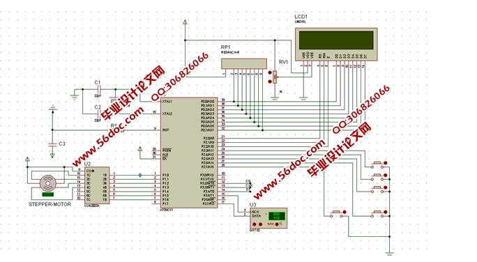
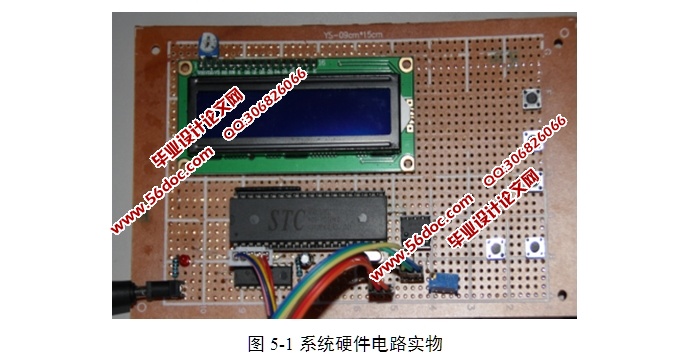
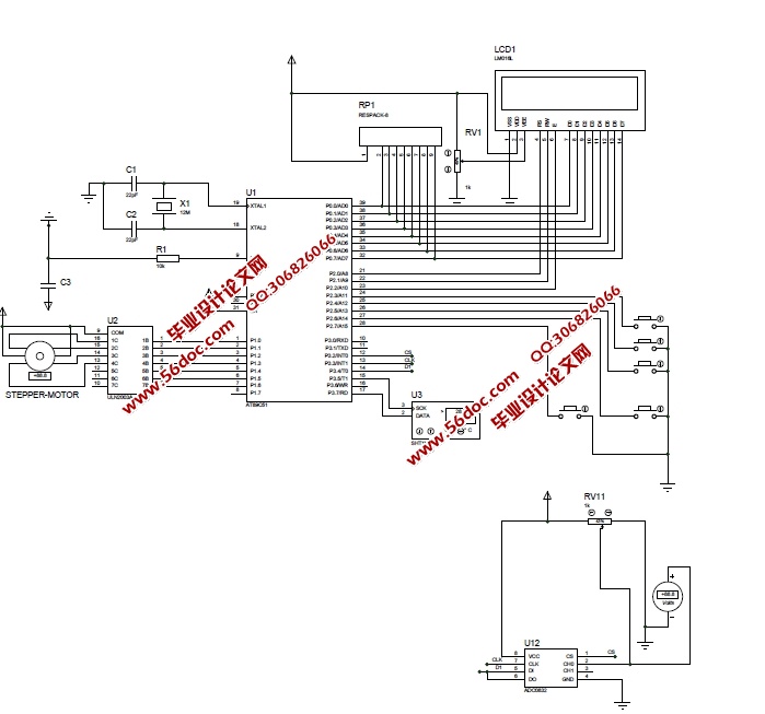
基于51单片机的饲料库防霉系统设计,采用以AT89C51单片机为核心的处理器。它和振荡电路、复位电路组成了最小控制系统。系统使用液晶LCD1602作为显示单元,采用DHT11作为测量环境温度和湿度的传感器,MQ-2作为烟雾传感器,使用ULN2003作为步进电机驱动模块。系统共设置5个按键,按从左到右的顺序,按键1实现手动开门;按键2实现手动关门;按键3是开启功能设置;按键4是加数键;按键5是减数键。运行时,能够实现温度达到30℃以上时,步进电机正转,温度低于25℃时,步进电机反转,同时液晶屏显示现在的温度和湿度。为防止意外饲料库意外失火,本设计添加了烟雾报警器MQ-2,该传感器反应速度快,侦测范围广,驱动电路简单,优异的稳定性,易于操作,能达到安全目的。
关键词:饲料;温湿度检测;单片机
Abstract
This essay is designed to detect the temperature and humidity of feed stores. Through the single chip microcomputer processing, MCU will drive motor to control the door of feed stores. So we can control the temperature and humidity of feed stores. Several methods to prevent feed goes moldy are analyzed. We’d better adopt the method of changing the surrounding environment. This is a method that tests on surrounding environment by using DHT11. In the case of the system which has a sufficient electricity supplied, the result of DHT11 tests on temperature and humidity is reliable. It is a device that contains the temperature and humidity of the calibration of the digital signal output composite transmission.
For the feed mildew proof system, we take AT89C51 as the core processor. The minimum control system is consists of MCU、oscillation circuit and reset circuit. The system uses LCD1602 as a display unit and uses DHT11 as the sensor. MQ-2 which is a smoke sensor and ULN2003 which is a stepper motor driver module are two modules in the system. The system sets up 5 buttons. According to the order from left to right, the first button can open the door manually; the second can close the door manually; the third button is the function key; the fourth is the addend key and the fifth is the reduction key. In the running time, the motor is controlled to rotate in the forward direction when the temperature is over 30℃. And when the temperature is below 25℃, the motor is controlled to rotate in the adverse direction when the temperature above 30℃. At the same time, the current time is shown on the LCD1602. This design adds the smoke alarm MQ-2, with the response speed highly, wide range, simple drive circuit, excellent stability, easy operation. According to MQ-2, the system can achieve the purpose of security.
Key words:Forage;temperature and humidity detection;MCU
本文研究内容
由于温度湿度是一种自然的能量反应,其变化一般不易及时察觉,日常感觉中的变换也不会立即反应出来,因此对饲料环境的温湿度检测至关重要。对环境检测的不当将直接影响饲料的使用效益和质量,甚至直接伤害畜生和人体健康,严重情况下还会导致死亡。对温湿度进行实时监测和及时的调整成为饲料库环境工作的一个极为重要方面,饲料库防霉设计的势在必行。
本文选取环境的温度和湿度等指标同时进行进行检测,对于检测温湿度技术,国内外主要包括几种方法进行对比分析,一种是采用模拟信号,第二种是采用数字信号,目前来看数字信号是检测温湿度比较直接并且可靠的方法。通过电信号的变换与采集周期测算,采用以AT89C51单片机为核心的处理器,以震荡电路和复位电路组成的单片机最小系统为控制单元,液晶LCD1602作为显示单元,采用DHT11传感器测量环境温度和湿度,MQ-2作为烟雾传感器,选择ULN2003作为步进电机驱动模块。
系统总体方案设计
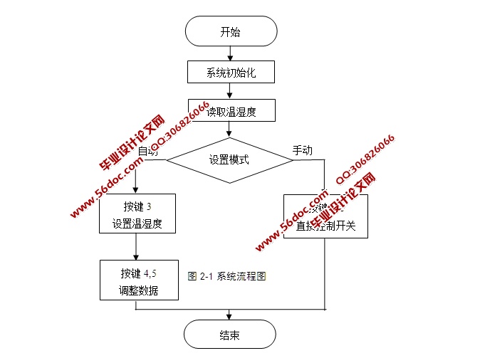
本系统的MCU使用了ATMEL公司的低功耗单片机AT89C51。主程序中仅完成了系统的初始化和开始的显示部分,然后就进入待机模式。其他功能模块都在中断服务子程序中完成。当产生中断时,MCU被唤醒并执行相应的中断服务子程序,从中断子程序返回后,系统又进入到待机模式,并关闭显示设备,节省电量。整个程序的设计使系统在绝大多数时间都处于最低功耗状态。整个程序用全部用C语言编写,使用模块化的设计方法,把各个模块相关的程序放在一个文件中,便于分块调试和管理,缩短了调试周期,增加了程序的可移植性和可剪裁性[3]。
在主程序中,首先关闭了看门狗和总中断,避免了在初始化过程中看门狗或其他中断导致单片机复位,使初始化无法完成。初始化过程分模块进行,增加了程序的可读性,而已便于分块调试,缩短了调试周期。整个系统软件需要对温度传感器DHT11、报警器、饲料库门控制系统进行管理。温度传感器DHT11为数字式温度传感器,直接与单片机的串口连接来读取温度[4]。以上所有模块均在主程序中完成初始化过程

目 录
第1章 概述 1
1.1 课题背景 1
1.2 研究现状与方向 1
1.3 本文研究内容 3
第2章 防霉菌设计目标和任务 4
2.1 防霉设计主要实现的目标 4
2.2 系统总体方案设计 5
2.3 本章小结 6
第3章 系统硬件电路设计 7
3.1 单片机模块设计 7
3.2 其它模块设计 10
3.3 本章小结 19
第4章 软件系统设计 20
4.1 模块程序流程图 21
4.2 程序设计 23
4.3 本章小结 23
第5章 系统安装与调试 24
5.1 系统硬件组装 24
5.2 软件开发调试 25
5.3 本章小结 32
结论 33
参考文献 34
致 谢 35
附录1:电路图 36
附录2:程序 37
|


