基于51单片机的计算器设计(含电路图,程序)(课题申报表,任务书,开题报告,中期检查表,外文翻译,论文11200字,程序,答辩PPT)
摘 要
计算器一般是指“电子计算器”,能进行数学运算的手持机器,拥有集成电路芯片,结构简单,功能较弱,但由于它使用方便、操作简单、价格低廉,因而广泛运用于商业交易中,也是必备的办公用品。
近年来随着科技的飞速发展,单片机的应用正在不断深入,同时带动传统控制检测技术日益更新。在实时检测和自动控制的单片机应用系统中,单片机往往作为一个核心部件来使用,但仅单片机方面的知识是不够的,还应根据具体硬件结构、软硬件结合,来加以完善。因此,单片机的应用已经越来越贴近生活,用单片机来实现一些电子设计也变得容易起来。计算器在人们的日常中是比较的常见的电子产品之一。可是它还在发展之中,以后必将出现功能更加强大的计算器,基于这样的理念,本次设计是用单片机来设计的计算器。该设计系统是以 AT89S52 为单片机, P1 口作为输入端,外接 4X4 的键盘。通过键盘扫描来对输入数的控制,在 P0 口、P2 口接了驱动电路,用来保证 LCD 的工作正常。计算器将完成的功能有加,减,乘,除等功能。
关键词:计算器;单片机;LCD;矩阵键盘
Abstract
Calculator generally refers to the electronic calculator, and the term is introduced to China by the Japanese. The calculator with the IC chip, simple structure, and weak function is able to perform mathematical operations on handheld machine. But it is easy using, simple operation and low price. So it is widely used in commercial transactions, and is also an essential office supplies.
With the rapid development of science and technology in recent years, the application of SCM is the deepening and promote the traditional controlling detection technologies that are increasingly updated. In real-time detection and automatic control of microcomputer application system, the microcontroller is often used as a core component to use, but only the knowledge of the microcontroller is not enough, and should be based on the specific hardware architecture, hardware and software combination to make it perfect. So the application of SCM is more and more close to life, so using of single chip to achieve some electronic designs also become easy. In the people daily life the calculator is one of the common electronic products. But it is still in development, it will become more powerful calculator in the future. According to such idea, the design is that SCM design calculator. The design system is based on AT89S52 microcontroller, P0 port as input, external 4X4 keyboard. In P1, P2mouth is connected with the drive circuit to ensure the normal work of LED. The calculator will complete add, subtract, multiply, divide and other function.
Keywords: calculator, MCU, LCD, Matrix keyboard
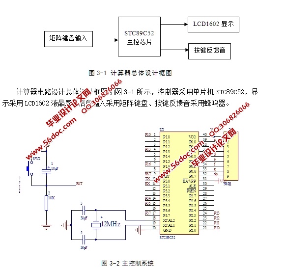
计算器电路设计总体设计框图如图3-1所示,控制器采用单片机STC89C52,显示采用LCD1602液晶屏,信息输入采用矩阵键盘、按键反馈音采用蜂鸣器。
1602采用标准的16脚接口,其中:
第1脚:GND为电源地
第2脚:VCC接5V电源正极
第3脚:V0为液晶显示器对比度调整端,接正电源时对比度最弱,接地电源时对比度最高(对比度过高时会 产生“鬼影”,使用时可以通过一个10K的电位器调整对比度)。
第4脚:RS为寄存器选择,高电平1时选择数据寄存器、低电平0时选择指令寄存器。
第5脚:RW为读写信号线,高电平(1)时进行读操作,低电平(0)时进行写操作。
第6脚:E(或EN)端为使能(enable)端,高电平(1)时读取信息,负跳变时执行指令。
第7~14脚:D0~D7为8位双向数据端。第15~16脚:空脚或背灯电
源。15脚背光正极,16脚背光负极。
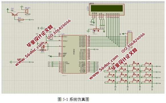
与单片机连接如图3-3所示:
特性:
3.3V或5V工作电压,对比度可调内含复位电路提供各种控制命令,如:清屏、字符闪烁、光标闪烁、显示移位等多种功能有80字节显示数据存储器DDRAM内建有192个5X7点阵的字型的字符发生器CGROM8个可由用户自定义的5X7的字符发生器CGRAM特征应用微功耗、体积小、显示内容丰富、超薄轻巧,常用在袖珍式仪表和低功耗应用系统中。

目 录
第1章 概述 1
1.1单片机发展现状 1
1.2计算器系统现状 2
1.3选题意义及现状 2
1.4本文主要研究内容 2
第2章 总体方案及设计 3
2.1设计目的 3
2.2设计任务 3
2.3方案构思 3
2.4方案比较与选择 4
2.5系统总体模块图 4
2.6本章小结 4
第3章 系统的硬件设计与实现 5
3.1 系统总体设计框图 5
3.2.单片机主控制模块的设计 5
3.3 LCD1602显示模块的设计 5
3.4 矩阵键盘模块设计 7
3.5 本章小结 9
第4章 软件设计 10
4.1显示程序设计 10
4.2键扫程序设计 10
4.3清零程序设计 10
4.4声音开关程序设计 13
4.5总体设计 14
4.6 本章小结 15
第5章 系统仿真及原理图 16
5.1 Proteus仿真 16
5.2 本章小结 18
第6章 系统调试 19
6.1硬件常见故障 19
6.2软件调试 19
结论 21
致 谢 22
参考文献 23
附录 24
程序 24
|


